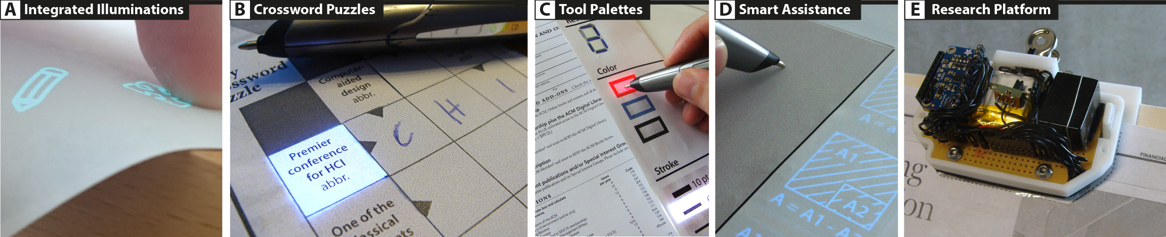
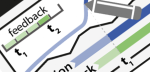
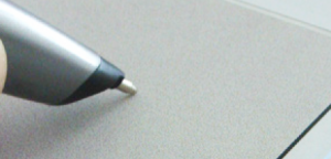
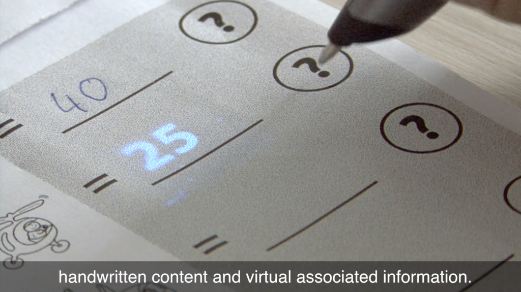
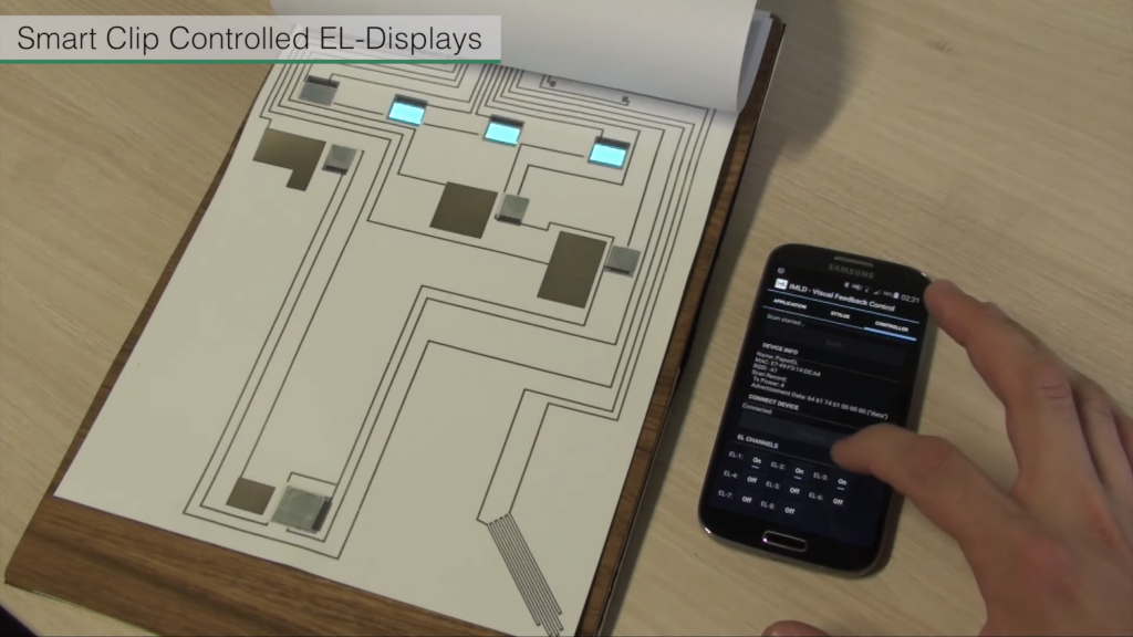
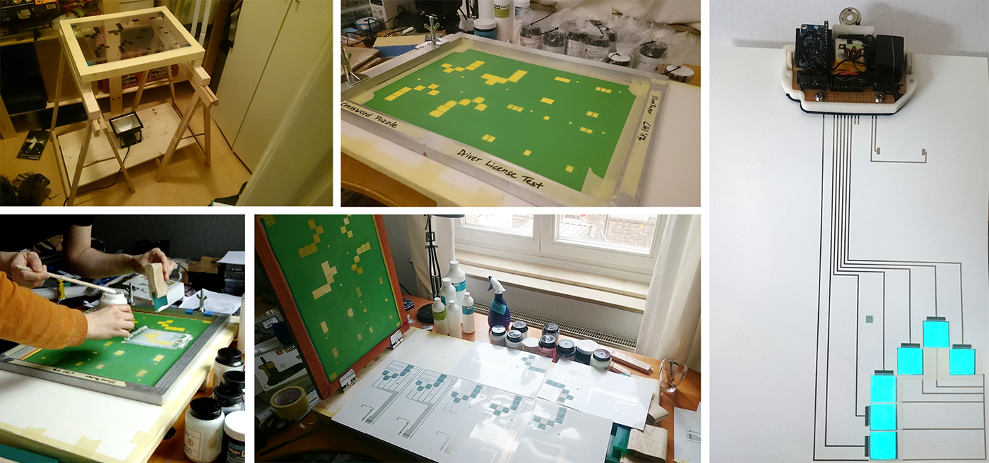
The IllumiPaper research platform (E) provides paper-integrated visual feedback without losing the sensory richness and flexibility of paper (A) and supports several applications including educational grid puzzles (B), interactive tool palettes (C) or even math exercise sheets (D).
Publications

@inproceedings{Klamka2017d_IllumiPaper_ISS,
author = {Konstantin Klamka and Wolfgang B\"{u}schel and Raimund Dachselt},
title = {Illuminated Interactive Paper with Multiple Input Modalities for Form Filling Applications},
booktitle = {Proceedings of the 2017 ACM International Conference on Interactive Surfaces and Spaces},
series = {ISS '17},
year = {2017},
month = {10},
isbn = {978-1-4503-4691-7},
location = {Brighton, United Kingdom},
pages = {434--437},
numpages = {4},
doi = {10.1145/3132272.3132287},
url = {https://doi.org/10.1145/3132272.3132287},
acmid = {3132287},
publisher = {ACM},
address = {New York, NY, USA},
keywords = {Digital pen and paper, electroluminescence, augmented paper, visual feedback, Anoto, form filling, printed electronics}
}List of additional material

@inproceedings{klamka2017c,
author = {Konstantin Klamka and Raimund Dachselt},
title = {IllumiPaper: Printed Displays for Novel Digital Pen-and-Paper User Interfaces},
booktitle = {Mensch und Computer 2017 - Workshopband},
year = {2017},
month = {9},
location = {Regensburg},
pages = {625--628},
numpages = {4},
doi = {10.18420/muc2017-demo-0289},
url = { https://doi.org/10.18420/muc2017-demo-0289},
publisher = {Gesellschaft f\"{u}r Informatik e.V.},
address = {Regensburg},
keywords = {digital pen and paper, electroluminescence, visual feedback, Anoto, augmented paper}
}List of additional material
@inproceedings{klamka2017a,
author = {Konstantin Klamka and Raimund Dachselt},
title = {IllumiPaper: Illuminated Interactive Paper},
booktitle = {Proceedings of the SIGCHI Conference on Human Factors in Computing Systems},
year = {2017},
month = {5},
location = {Denver, CO, USA.},
pages = {5605--5618},
numpages = {14},
doi = {10.1145/3025453.3025525},
url = {http://dx.doi.org/10.1145/3025453.3025525},
publisher = {ACM},
keywords = {Digital pen and paper, electro-luminescence, pen interaction, visual feedback, Anoto, thin-film display, augmented paper}
}@unpublished{klamka2017b,
author = {Konstantin Klamka and Raimund Dachselt},
title = {Demonstrating IllumiPaper: Illuminated Interactive Paper},
booktitle = {Accompanying CHI 2017 Interactivity Research Demo of the SIGCHI Conference on Human Factors in Computing Systems},
year = {2017},
month = {5},
location = {Denver, CO, USA.},
publisher = {ACM},
keywords = {Digital pen and paper, electro-luminescence, pen interaction, visual feedback, Anoto, thin-film display, augmented paper}
}List of additional material

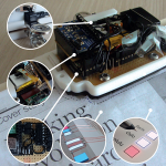
Table of Contents
This research project website provides additional information about the fabrication of our IllumiPaper system including the four main components of the digital stylus, our augmented papers, the smart clip and its charging module as well as the Android device. In the following, we provide a short table of contents with skip links to easily jump to all description parts:
Abstract
Due to their simplicity and flexibility, digital pen-and-paper solutions have a promising potential to become a part of our daily work. Unfortunately, they lack dynamic visual feedback and thereby restrain advanced digital functionalities. In this paper, we investigate new forms of paper-integrated feedback, which build on emerging paper-based electronics and novel thin-film display technologies. Our approach focuses on illuminated elements, which are seamlessly integrated into standard paper. For that, we introduce an extended design space for paper-integrated illuminations. As a major contribution, we present a systematic feedback repertoire for real-world applications including feedback components for innovative paper interaction tasks in five categories. Furthermore, we contribute a fully-functional research platform including a paper-controller, digital pen and illuminated, digitally controlled papers that demonstrate the feasibility of our techniques. Finally, we report on six interviews, where experts rated our approach as intuitive and very usable for various applications, in particular educational ones.
Video
Extended Technical Schema
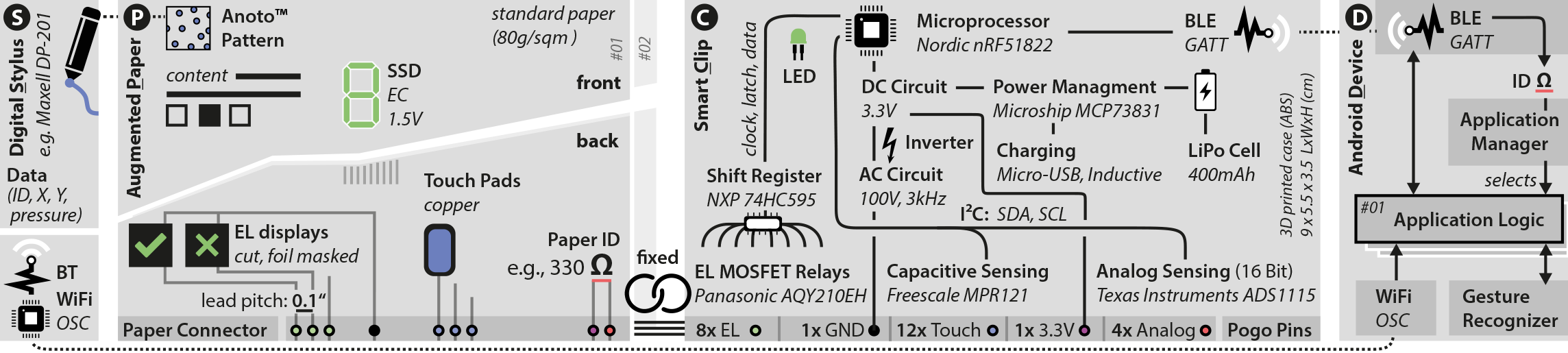
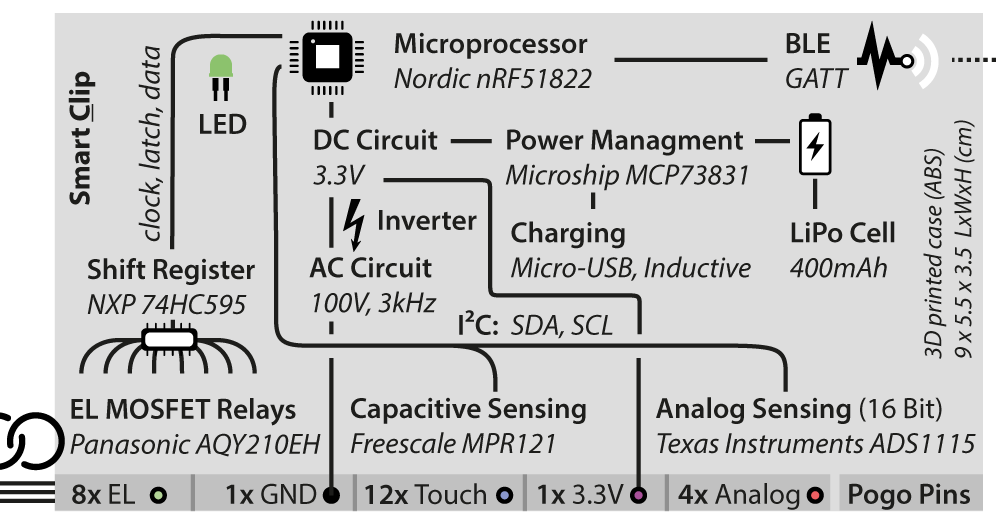
Technically, our setup consists of four components: A digital stylus (S), different augmented papers (P), a smart controller clip (C) and an Android device (D).
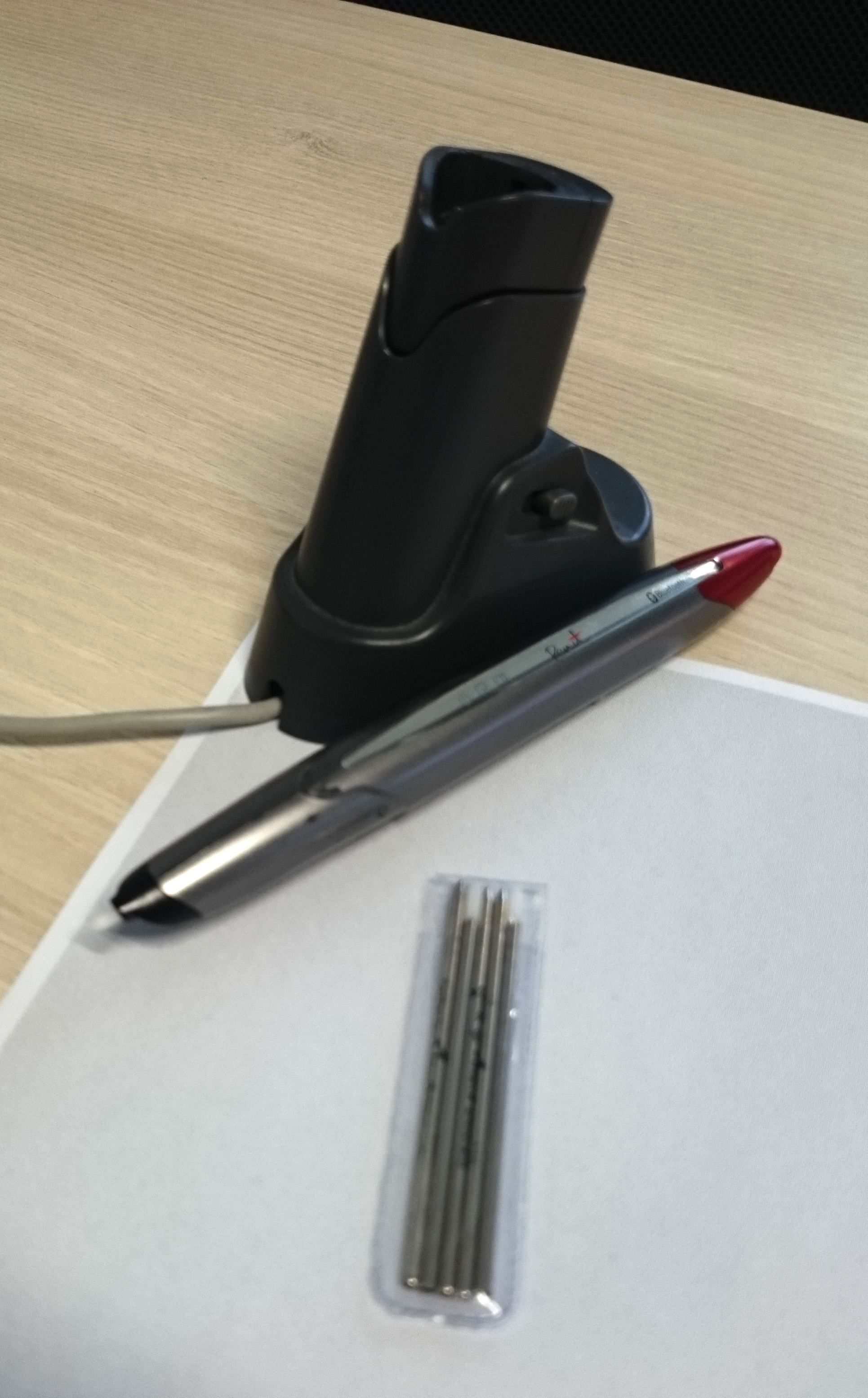
 Digital Stylus
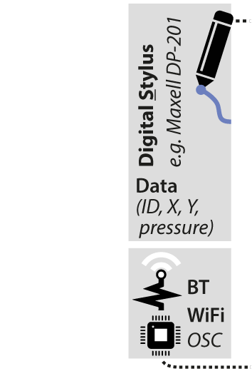
We used the Anoto-based digital pen Maxell DP-201 for our project. However, it does not matter which model or sensor technology is used as along as the pen stream its position and state data.
We stream the following data values:
- unique pen identifier
- x and y position
- pressure
- event type
- timestamp
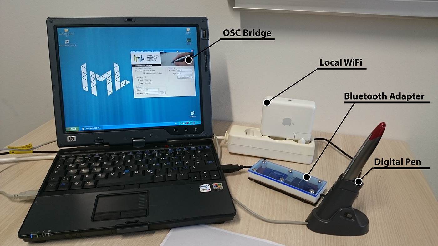
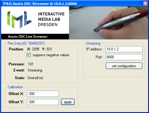
Data Streaming
In order to stream the pen data, we built a thin application that receive stroke and state data via Bluetooth from the pen and forwards the data in the Open Sound Control (OSC) format via WiFi to our mobile Android application.
Components*
| Component | Model |
|---|---|
| Notebook | HP Compaq tc4400 |
| Bluetooth Adapter | Ednet Bluetooth USB V2.0 C2 Adapter |
| Digital Stylus | Maxell Penit DP-201 Digital Pen |
| Local WiFi | Apple AirPort Express Base Station |
*Please note: In order to save costs, we used hardware that exist in our research lab. Of course, you can use newer models and components, however, this is not necessary.
Setup
Please note: Since Anoto™ introduced the commercial Android Live SDK, pens can be paired directly, which enable even faster mobile setups.
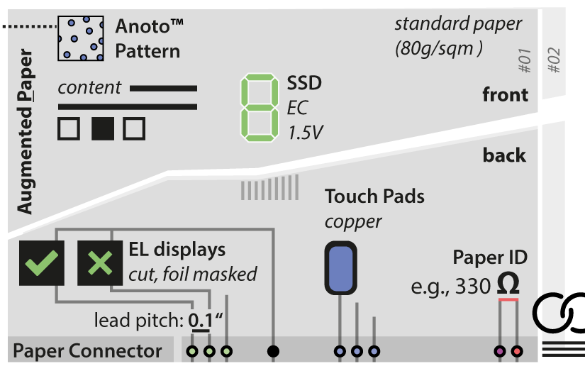
 Augmented Papers
Paper Traces
| Method | Conductive Material | Prototyping Level |
|---|---|---|
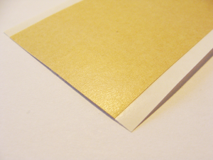
| A: Copper Tape | Copper Foil Tape with Conductive Adhesive – 6mm | easy, cheap and fast |
| B: Conductive Ink Pen | Circuit Scribe Pen | easy, cheap and fast |
| C: Conductive Inkjet-Printing | Mitsubishi Imaging (MPM) Silver Nanoparticle Ink | advanced, higher initial setup costs |
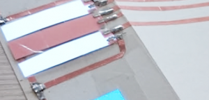
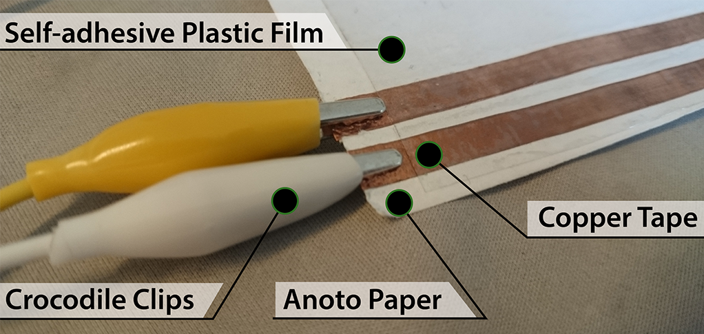
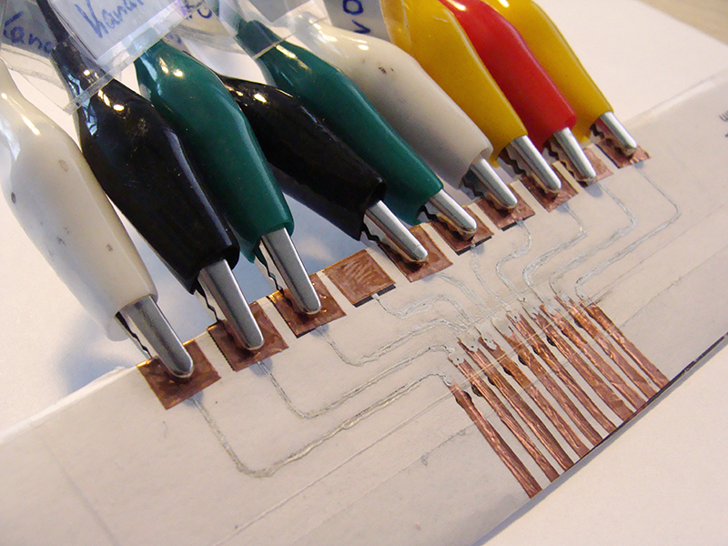
- Method: Copper tape traces
We used self-adhesive copper tape to prototype high-conductive traces by sticking this tapes on standard paper. However, the self-adhesive copper tape looks a little bit cumbersome at some points, it is a good starting point to initially test a IllumiPaper design.
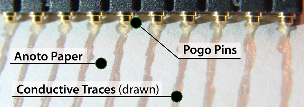
- Method: Conductive ink drawn traces
Conductive ink pens (e.g., with circuitscribe or Bare Conductive Ink) enable instant circuit sketching. In addition, conductive ink pens can be combined with other types of trace fabrication (e.g., copper tapes or printed traces). We use conductive z-axis tape to bridge the types or to connect a component or module.
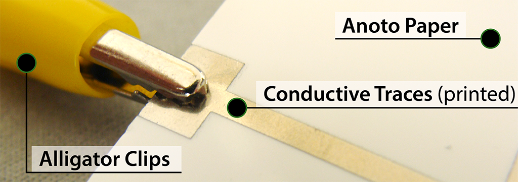
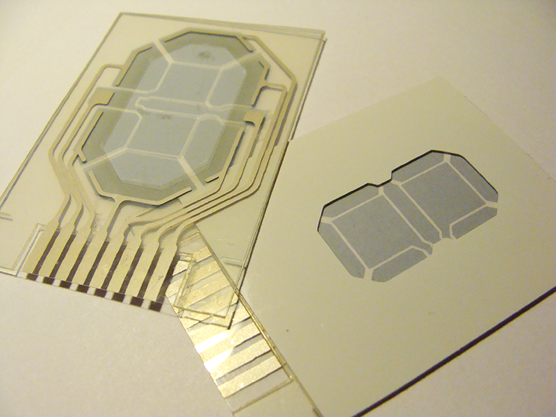
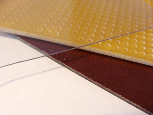
- Method: Conductive inkjet-printed traces
In addition, traces can be directly inkjet-printed on paper with conductive inks. These advanced fabrication method can be used to increase the degree of quality and integration of IllumiPapers.
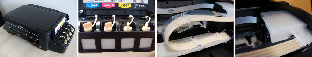
We used a Epson ET-2500 for the conductive ink printing. The tubes, ink tanks and the printer head of the Epson work well since the parts are clean and empty (many thanks to the HCI group in Saarbrücken for the help). With the Brother MFC-480DW, we have bad experiences since the printers already come, to our surprise, with pre-charged ink (printer head, printer tubes). This would contaminate the conductive ink.
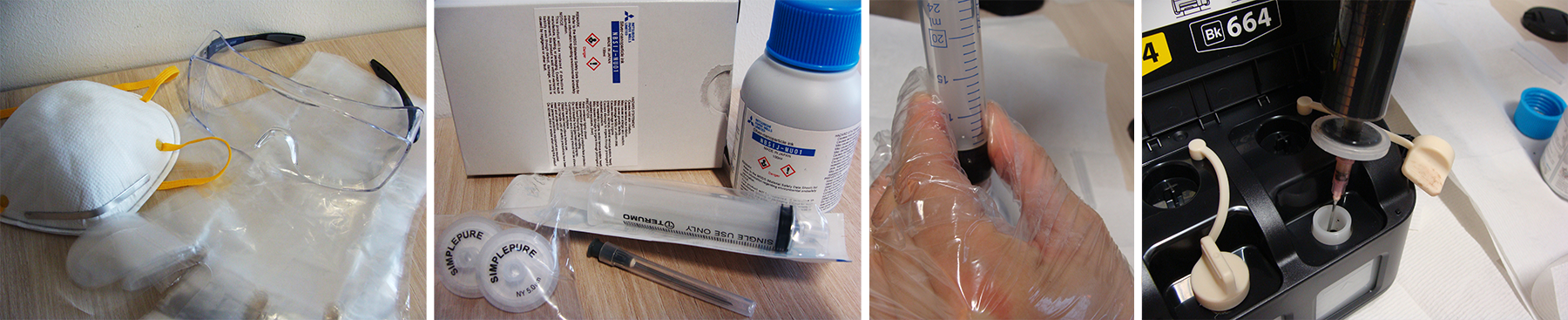
Please make sure that you respect necessary safety instructions of the silver-nanoparticle ink.
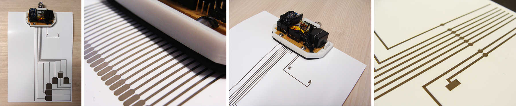
Our smart-clip with a printed inkjet-printing sheet. The conductive traces and electrodes serve as a basis for screen printed EL substrates.
Paper Connectors
| Image | Part | Description |
|---|---|---|
 |
3M Z-Axis Conductive Tape 9703 – 2″x6″ (50mm x 150mm) Strip | |
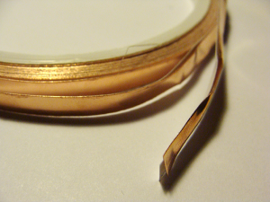 |
Self-adhesive Copper Tape | We used self-adhesive copper tape to prototype high-conductive traces by sticking this tapes on standard paper. However, the self-adhesive copper tape looks a little bit cumbersome at some points, it is a good starting point to initially test a IllumiPaper design. Further advanced fabrication methods such as conductive inkjet printing can be the next step to achieve a better integration. |
 |
0.1″ alligator clip breakouts |
Paper Displays
| Image | Part | Description |
|---|---|---|
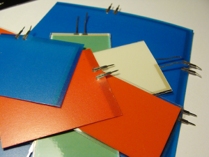 |
Cuttable multi-contact electroluminescent foil with prefabricated contacts | We used multi-contact electroluminescent foils with prefabricated contacts in different colours (e.g., red, blue, white) that can be easily cut and/or covered with printed self-adhesive transparent foil. This allows us to test several illuminations in a fast way. |
 |
Cuttable multi-contact electroluminescent foil with customizable contacts | |
 |
ELastoLite Panel – 5×3 inches – Orange and ELastoLite INV133 Inverter |
In order to investigate the flexibility of electroluminescent displays, we tested paper-attached ELastoLite panels that are very robust and crushable. |
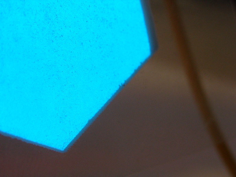 |
Screen printed electroluminescent display | We experimented with screen printed electroluminescent displays that allow paper displays on the paper itself.
Besides the related work that is mentioned in detail in our paper (e.g., PrintScreen), there is a great Electroluminescent Screen Video Tutorial from the Zurich University of the Arts (ZHdK) (Interaction Design Program) that shows the fabrication process in detail. |
 |
Ynvisible Electrochromic Seven-segment Display | We used flexible transparent electrochromic e-paper like displays from Ynvisible that can be also printed directly on paper. Electrochromic materials change their color when electricity is applied. In our case, the seven-segment display gets blue. |
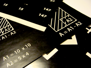 |
Printed Self-adhesive Transparent Foil | We used printed self-adhesive transparent foils to cover the electroluminescent foils. In transparent regions the electroluminescent panel shines through, while the black-printed areas work as stencils and block the illumination. This allows us to test several illuminations in a fast and easy way. The foils are printed in our local copyshop. |
EL Screen Printing
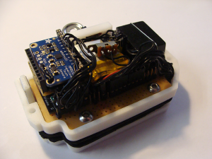
 Smart Clip
Tool List
- Solder Iron (we used a 16 W Ersa TIP 260)
- 3D printer (we used a PP3DP UP! Mini)
- Rotary Multitool
Part List
| Image | Part | Description |
|---|---|---|
 |
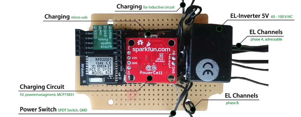
SparkFun Power Cell – LiPo Charger/Booster PRT-11231 | We used a power management board from Sparkfun with a Microship MCP73831 chip. This allows us, versatile charging capabilities including micro-usb and inductive charging. In order to avoid any damage on the micro-usb port on the board during the development (cf. Sparkfun customer reviews), we strengthen this part with a custom-printed part. |
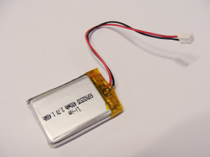 |
LiPo Accu – 400mAh PRT-10718 | We used a standard 400mAh lithium polymer battery to power the smart clip to power the smart clip. The battery provides electric power to both: to the microprocessor including its associated logic parts and the high-voltage frequency AC circuit that is generated by our EL inverter for the EL illumination. |
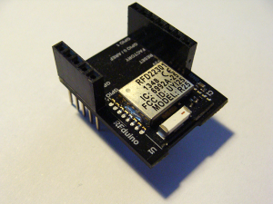 |
RFduino | For our smart controller clip, we used the RFduino microcontroller which basically consists of a Nordic Semiconductor nRF51822 chip with a Arduino-compatible bootloader. For rapid prototyping, we decided to use the bigger version with 0.1″ pin breakouts. However, for further miniaturizations a smaller SMD version of the microcontroller (size of a finger-tip) is still available. |
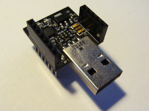 |
FTDI Programmer | In order to upload new firmware to our research platform, we used this tiny FTDI programmer that can be directly stacked RFduino. However, every other 3.3V FTPI programmer works as well. You have simply to hook up the following pins: receive pin (RX, 0), transmit pin (TX, 1), reset pin, ground and +3V. |
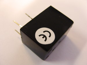 |
EL-Inverter Conrad WE-50: 5 V/DC black | We used a classic 5V EL-Inverter that produces 110 V/AC with a frequency of 700 Hz at output. This inverter can illuminate an overall surface area up to 105 cm². |
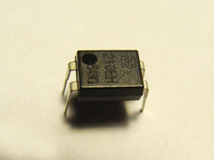 |
PhotoMOS-Relay, Panasonic AQY210EH | Optoisolators are often too slow to turn off at the very brief zero crossings when it is fed with ~1kHz AC current. Therefore, we use a more appropriate OptoMOS SSR switching elements to control the EL segments and handle the brief zero crossings. |
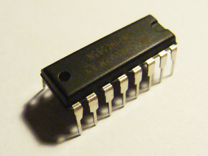 |
Adafruit 74HC595 Shift Register | To extend the limited GPIO pins of our microcontroller, we used shift register to extend the addressable digital channels, which we need, e.g., for our EL channels. Therefore, we used the popular Adafruit 74HC595 shift register, which are basically Texas Instrument 74HC595 Shift Register. |
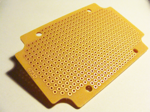 |
Prototyping PCB Phenolic paper, 0.1″ (2.54mm), 98003C12 | We used these prototyping boards as a basis for our circuits. 80 mm x 52 mm 35 µm Contact spacing 2.54 mm |
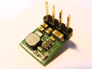 |
Pololu 3.3V, 600mA Step-Down Voltage Regulator D24V6F5 | Since our EL-Inverter requires 5V and our microcontroller 3.3V, we used a step-down voltage regulator to provide power to both from our power management board. |
| Adafruit 12-Key Capacitive Touch Sensor Breakout – MPR121 | We used the MPR121 chip (hooked up via I2C) to handle up to 12 individual touch pads. | |
| ADS1115 16-Bit ADC – 4 Channel with Programmable Gain Amplifier | We integrated the ADS1115 chip (hooked up via I2C) to extend up to 4 single-ended high-precision input channels. We used the additional ADC channels to sense our resistive paper flex gestures. | |
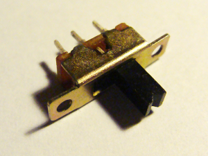 |
SPDT Switch | Simple SPDT switches serve us as on/off switches for our prototype. Therefore, we used one for our power management board and one for the battery to ensure extra-security while working on the open prototype. |
| Adafruit Inductive Charging Set – 5V @ 500mA max | We aim to support versatile charging capabilities and therefore integrate a inductive wireless charging module, which allows wireless charging. | |
 |
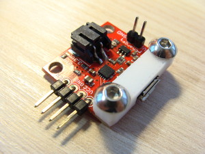
Mill-Max Pogo Pins: Single Row Series 819 (815-22-010) | To avoid loose contacts in our clip mechanism caused by surface irregularities or lateral shifts, we use small spring-loaded pogo pins. These tiny pogo pins compensate any contact problems. |
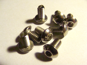 |
Makeblock Socket Cap Screw M4x8-Button Head | We used M4 Cap Screws with metric threads to fix our circuit boards to our custom-printed case parts. |
| Makeblock Plastic Spacer 4x7x2 | These tiny plastic spacer serve us to ensure minimal distances between our stacked circuit boards and thereby avoid bypasses. | |
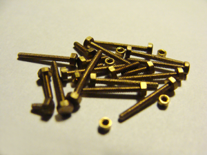 |
M1 screws and nuts | These very tiny screws are used to fix the bulldog with our prototyping PCB (the screws fit in the holes of the PCB). |
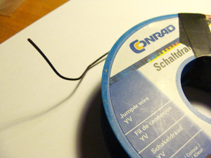 |
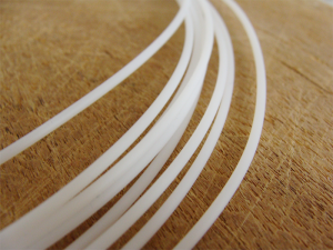
Jumper wire Yv, 1 x 0.20 mm², Black |
We used isolated standard jumper wire to hook up all sensors and output channels. However, there are not special requirements for the wires. Basically, you can use nearly every isolated cable. |
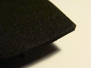 |
Foam Rubber Sheet, 2.0 mm x 200 mm x 300 mm, black |
We used pieces of foam rubber to ensure a secure hold of the paper in our smart clip. |
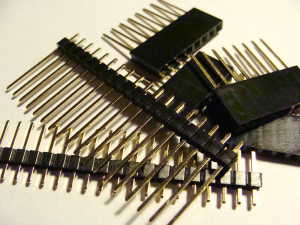 |
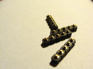
Standard 0.1″ (2.54mm) Pin Headers | We used several standard pin headers to design our smart prototype clip as flexible as possible without hardwiring all components. For example we built stackable shields with perfboards and pin headers to extend our research platform modular. |
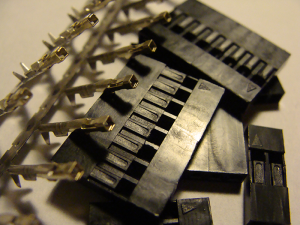 |
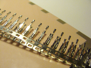
Standard 0.1″ (2.54mm) Crimp Connectors | In order to create custom cables for our research platform (e.g., flexible stackable EL channel pin layout), we used standard 0.1″ (2.54mm) crimp connectors. |
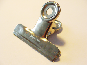 |
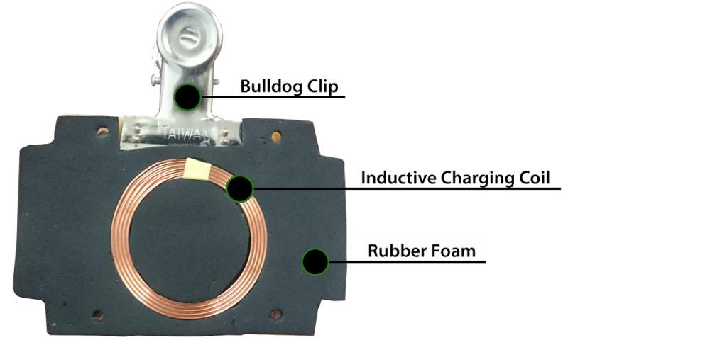
Bulldog Clip, metal, 50 mm |
We used this 50 mm bulldog clip for our smart clip. Therefore, we drilled holes with our rotary tool in the sides and mounted the prototyping PCBs with M1 screws and nuts to it. |
 |
Diverse boards including fibreboards, perfboards and plastic foils | |
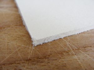 |
wood-pulp board, Gerstaecker 14758 | |
 |
PP3DP TierTime UP! ABS white 1,75mm 700g Filament for UP! | We used white ABS from PP3DP to print out all case parts for our IllumiPaper research platform. Of course, you can use any other filament, such as PLA, to fabricate the parts. However, you have to pay attention that the filament is supported by your 3D printer. |
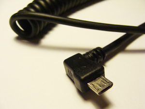 |
Angled Micro USB Cable | The angled micro usb cable fits perfectly into our 3D printed case and is used to charge our smart clip via USB. |
 |
USB extension cable | Since it is very tricky and annoying to plug the FTDI programmer directly into the computer or notebook, we used a USB extension cable (type A) to comfortably connect the FTDI programmer to upload new software updates on the micro-controller. |
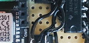
Microcontroller, Shift Register and PhotoMOS-Relays
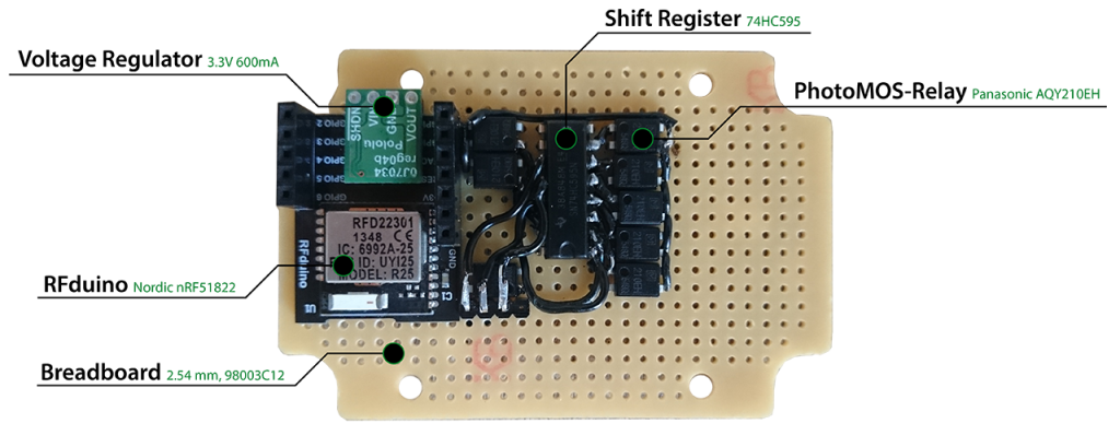
Note: Optoisolators are often too slow to turn off at the very brief zero crossings when it is fed with ~1kHz AC current. Therefore, we use a more appropriate OptoMOS SSR switching element (see PhotoMOS-Relay, Panasonic AQY210EH).
Charging Circuit & EL-Inverter
Circuit, back
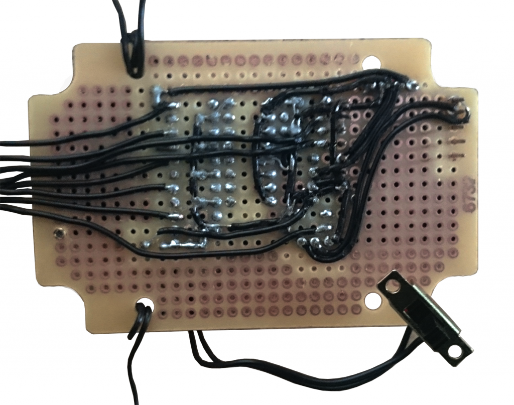
Note: In order to miniaturize the layout a custom printed circuit can save a lot space. We used for our circuit design rapid prototyping methods, which are cheap, easy (soldering + standard cables) and are available for everyone.
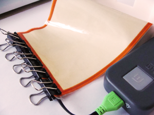
Inductive Charging
Case
We 3D printed basically three parts for our Smart Clip.
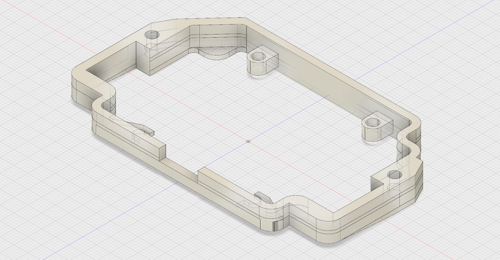
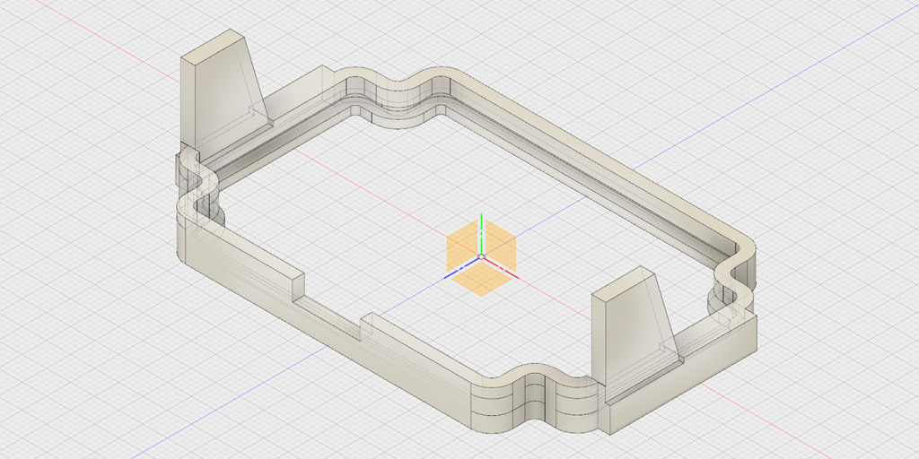
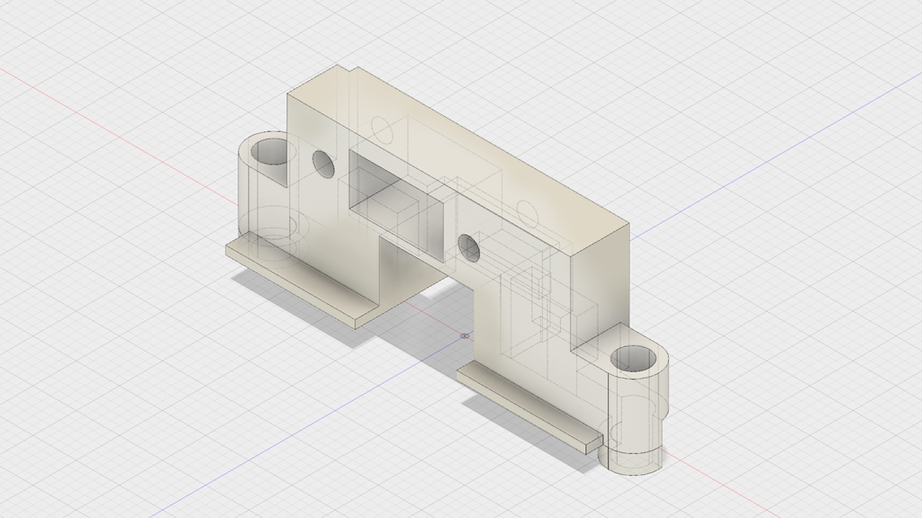
You can download the STL-Files here:
Charging Module
Tool List
- Solder Iron (we used a 16 W Ersa TIP 260)
- 3D printer (we used a PP3DP UP! Mini)
- Rotary Multitool
Part List
| Image | Part | Description |
|---|---|---|
| Adafruit Inductive Charging Set – 5V @ 500mA max | We aim to support versatile charging capabilities and therefore integrate a inductive wireless charging module, which allows wireless charging. | |
|
Makeblock Socket Cap Screw M4x8-Button Head | We used M4 Cap Screws with metric threads to fix our circuit boards to our custom-printed case parts. |
|
Jumper wire Yv, 1 x 0.20 mm², Black |
We used isolated standard jumper wire to hook up all sensors and output channels. However, there are not special requirements for the wires. Basically, you can use nearly every isolated cable. |
|
Foam Rubber Sheet, 2.0 mm x 200 mm x 300 mm, black |
We used pieces of foam rubber to fix all components in the charging module case. |
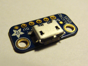 |
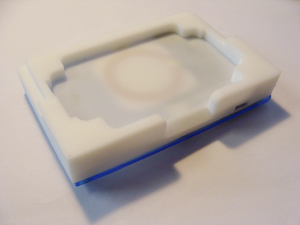
USB Micro-B Breakout Board | This tiny micro-usb breakout board allow us to seamlessly connect our inductive charging module. Our 3D printed case is designed that the board fits perfectly in. |
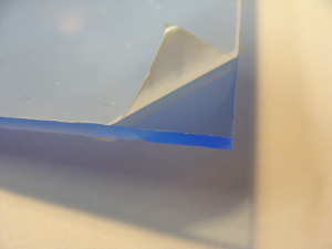 |
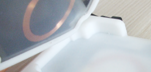
Acrylic glass GS, transparent, fluorescent blue |
This acrylic glass plate is used as a bottom plate for our inductive charging module. This blue shimmering plate allows to see the electronic and components inside the module. However, it is of course possible to use any other material such as normal acrylic glass, wood or metal. |
|
Angled Micro USB Cable | The angled micro usb cable that we already used to charge our smart clip via USB could also be used for our inductive charging module. |
|
PP3DP TierTime UP! ABS white 1,75mm 700g Filament for UP! | We used white ABS from PP3DP to print out all case parts for our IllumiPaper research platform. Of course, you can use any other filament, such as PLA, to fabricate the parts. However, you have to pay attention that the filament is supported by your 3D printer. |
Case
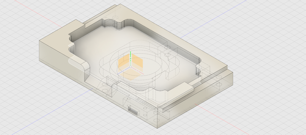
You can download the STL-Files here:
 Android Device
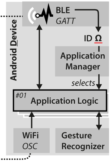
We used Vatavu et al.’s $P Point-Cloud Recognizer to process character- and glyph-based input.
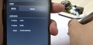
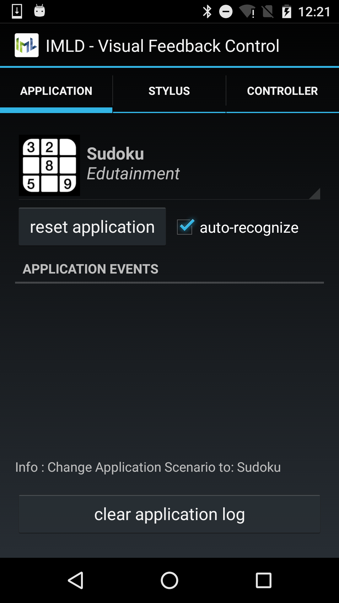
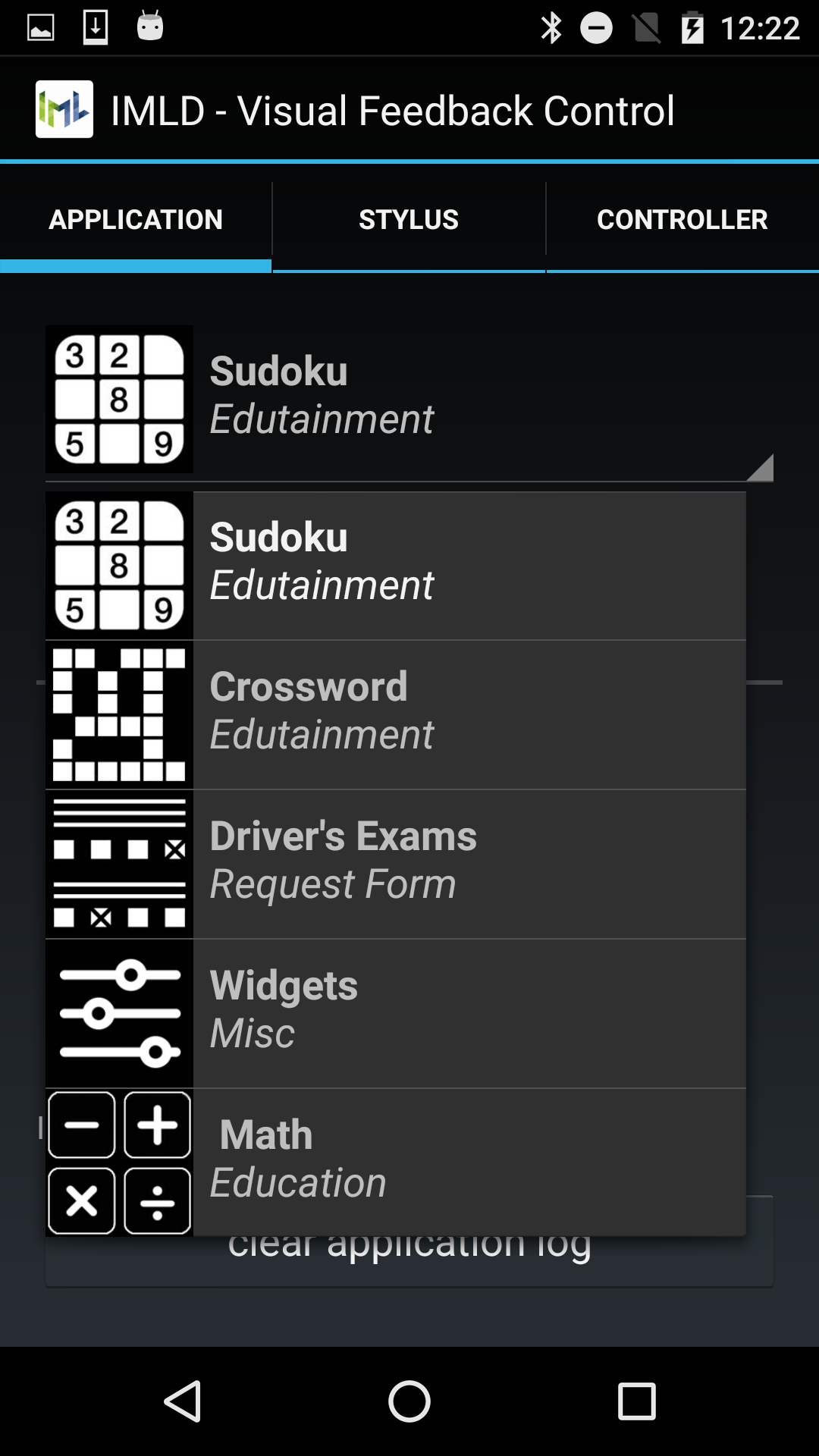
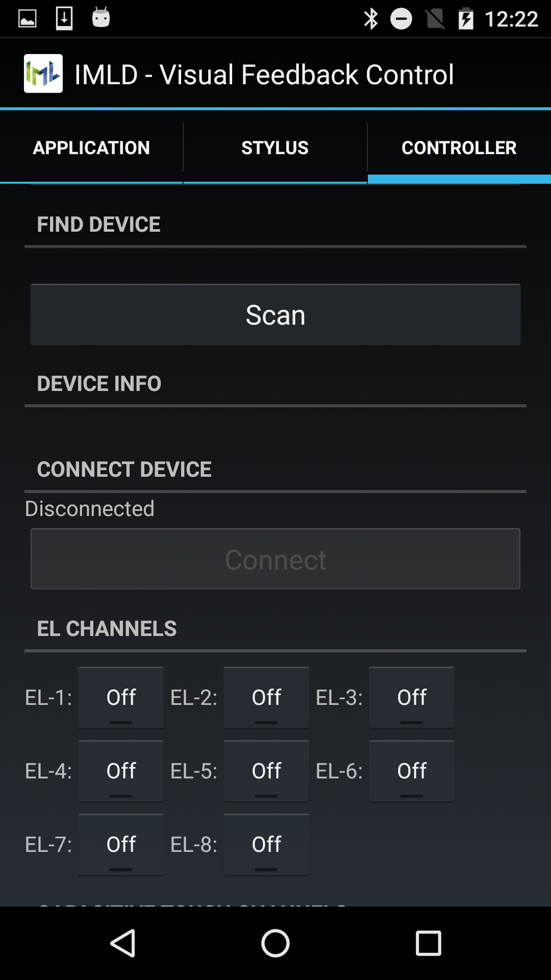
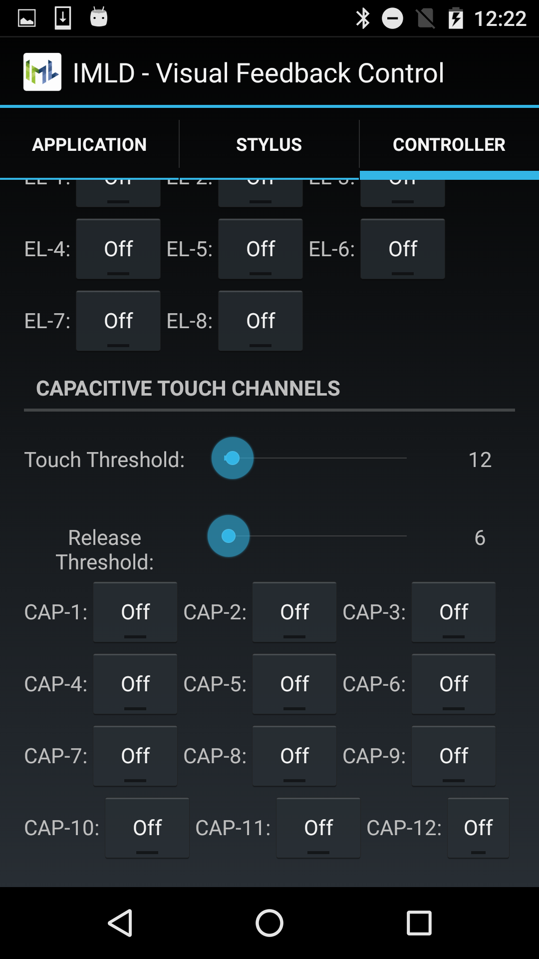
Application Screens
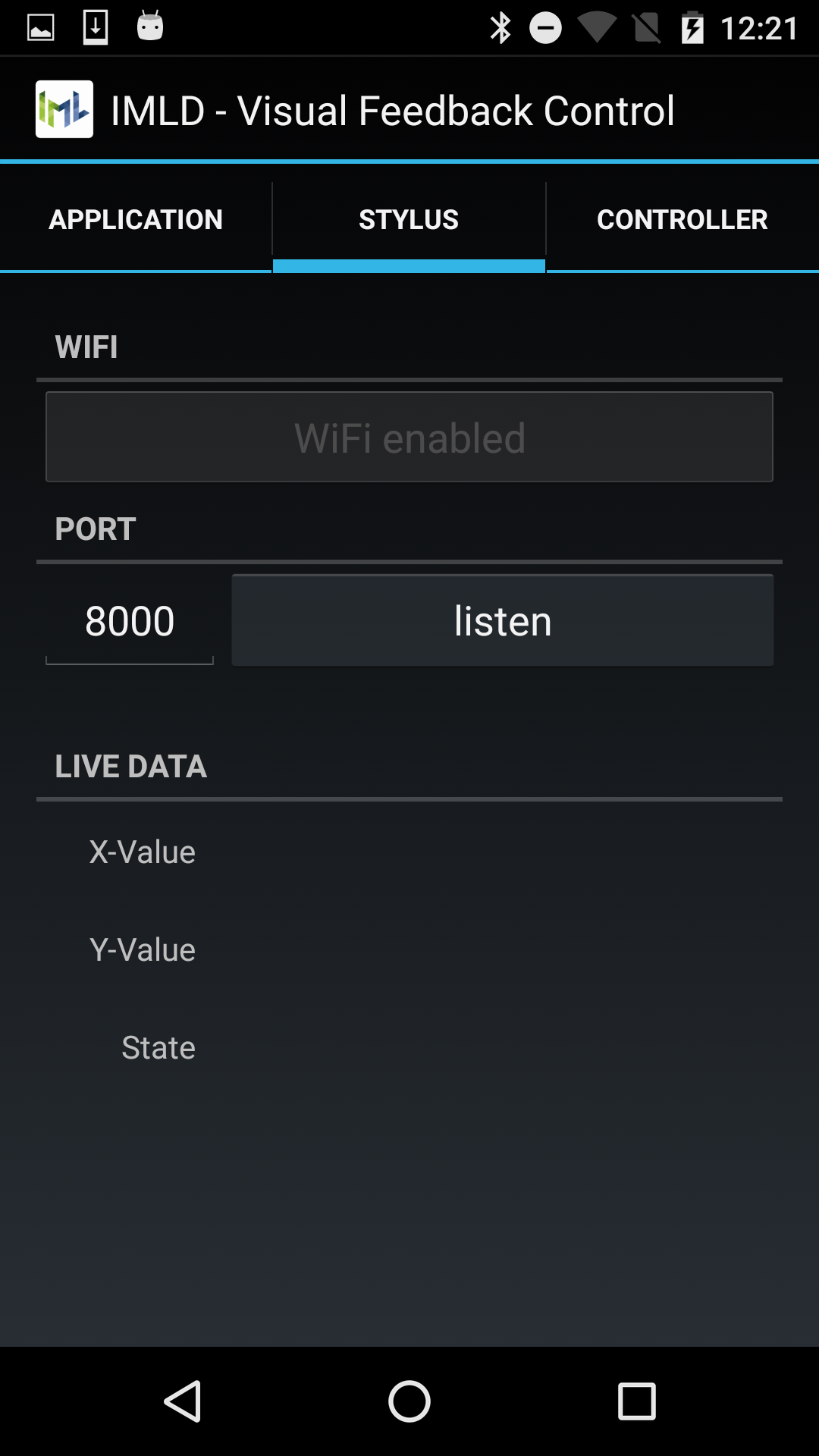
Our mobile Android application basically consists of three parts, which are implemented as tabs:
- An Application Tab (see figure 1+2)
- A Stylus Tab (see figure 3)
- A Controller Tab (see figure 4+5)
Our work was in part funded by the German Federal Ministry of Education and Research (Twenty20 — Partnership for Innovation, project fast, grant no. 03ZZ0514C).