Abstract
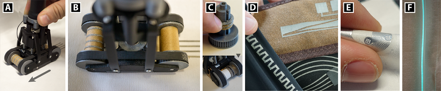
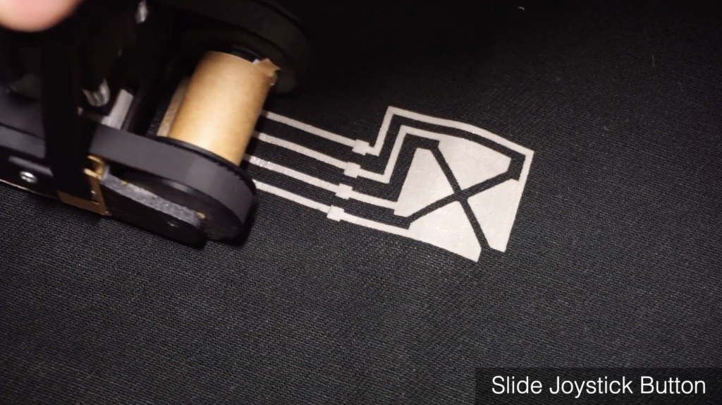
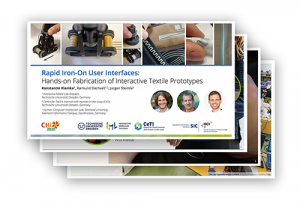
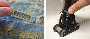
Rapid prototyping of interactive textiles is still challenging, since manual skills, several processing steps, and expert knowledge are involved. We present Rapid Iron-On User Interfaces, a novel fabrication approach for empowering designers and makers to enhance fabrics with interactive functionalities. It builds on heat-activated adhesive materials consisting of smart textiles and printed electronics, which can be flexibly ironed onto the fabric to create custom interface functionality. To support rapid fabrication in a sketching-like fashion, we developed a handheld dispenser tool for directly applying continuous functional tapes of desired length as well as discrete patches. We introduce versatile compositions techniques that allow to create complex circuits, utilize commodity textile accessories and sketch custom-shaped I/O modules. We further contribute a comprehensive library of components for input, output, wiring and computing. Three example applications, results from technical experiments as well as expert interviews demonstrate the functionality, versatility and potential of this approach.
Research Article
Recorded Talk (15 Min.)
You can also watch our shorter 3 minute presentation from the 2020 Virtual German CHI Week.
Slide Deck
Publications
@inproceedings{Klamka2020b,
author = {Konstantin Klamka and Raimund Dachselt and J\"{u}rgen Steimle},
title = {Rapid Iron-On User Interfaces: Hands-on Fabrication of Interactive Textile Prototypes},
booktitle = {Proceedings of the 2020 ACM Conference on Human Factors in Computing Systems},
year = {2020},
month = {4},
location = {Honolulu, Hawaii, USA},
doi = {10.1145/3313831.3376220},
publisher = {ACM}
}List of additional material
, Video
@inproceedings{Klamka2020c,
author = {Konstantin Klamka and Raimund Dachselt and J\"{u}rgen Steimle},
title = {Demonstrating Rapid Iron-On User Interfaces: Hands-on Fabrication of Interactive Textile Prototypes},
booktitle = {Proceedings of the 2020 CHI Conference Extended Abstracts on Human Factors in Computing Systems},
year = {2020},
month = {4},
isbn = {978-1-4503-6819-3/20/04},
location = {Honolulu, Hawaii, USA},
numpages = {4},
doi = {10.1145/3334480.3383139},
publisher = {ACM}
}List of additional material
, Video
Building Instructions
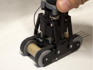
We first briefly describe the construction of the rapid iron-on tool and list all required components.
Next, we briefly present details for the fabrication of selected tapes and patches.
Rapid Iron-On Tool
Step 1: Prepare the Carriage Model
Required tools:
FDM 3D Printer, sandpaper (extra fine, 600 grit), fine-cut files, screwdriver (slotted), scissor and hobby knife, hacksaw (with metal saw blade).
| Image | Part | Description |
|---|---|---|
 |
High-temperature ABS Filament Print temperature: 270°C |
ABS can be mechanized, polished, sanded, drilled and glued and the finish is still good. In addition, it is extremely strong, more heat-resistant and it has certain flexibility. All of which makes it the perfect material for the rapid iron-on tool. We used Tiertime UP Fila ABS. |
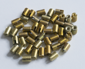 |
Threaded Inserts M2*0.4 / M4.5*0.5; 6mm; SKU: GS08040-01 |
We use threaded inserts to create reusable as well as strong screw connections between different 3D-printed parts (e.g., between the carriage and the spring-loaded iron) of the rapid iron-on tool. Available, for example, on Amazon. |
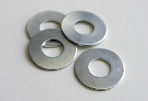 |
Washer d1=10.5mm; d2=25mm; s=1.3mm |
We placed a washer in the spring-loaded carriage to guarantee that the hot iron shaft never could have direct contact to the 3D-printed plastic carriage. Since the space inside the carriage is very limited, you also have to cut out a rectangle area to place the N20 motor. Washers can be bought at your local hardware store. |
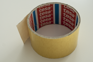 |
Double-sided Tape | In order to fix the washer to the carriage model, we used standard double-sided adhesive tape that is available in most crafting shop. |
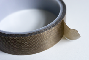 |
Glass Fabric Tape PTFE, 25mm x 10m, heat resistant up to 260°C, self-adhesive |
The bonding iron is very hot and in close proximity to the spring-loaded carriage. To add an additional protection layer for accidentally physical contacts of the iron, we partly add glass fabric tape made of polytetrafluoroethylene that is able to temporarily resist heat. For our current prototype, we used this one from Amazon. |
| 3D Model | Description |
|---|---|
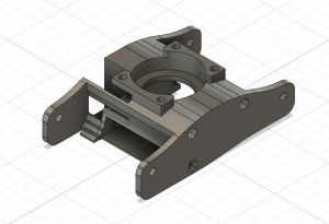 |
Carriage Model carriage.stl |
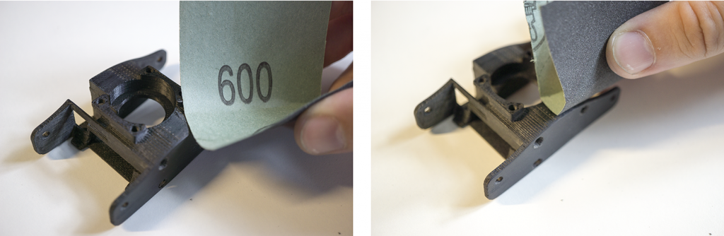
Remove support material and sand the model.
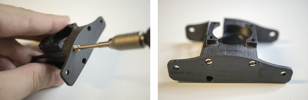
Screw in the four threaded inserts in the carriage model.
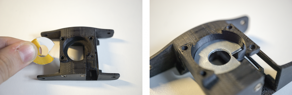
Place washer.
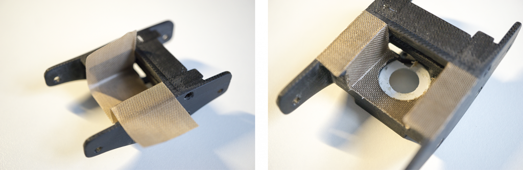
Create heat shield.
Step 2: Build RIO Tool Axes
Required tools:
FDM 3D Printer, sandpaper (extra fine, 600 grit), hacksaw (with metal saw blade), fine-cut files, hammer, mini clamps.
| Image | Part | Description |
|---|---|---|
|
High-temperature ABS Filament Print temperature: 270°C |
ABS can be mechanized, polished, sanded, drilled and glued and the finish is still good. In addition, it is extremely strong, more heat-resistant and it has certain flexibility. All of which makes it the perfect material for the rapid iron-on tool. We used Tiertime UP Fila ABS. |
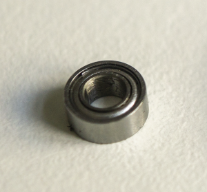 |
Bearings 3x6x2.5mm |
Available, for example, on Amazon. |
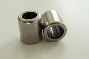 |
Freewheel Bearing Type: HF0612 dxDxB: 6x10x12mm |
In order to tighten the material spools, we used freewheel bearings that can be seamlessly rotated in one direction. A motion in the opposite direction is not possible. This allows us to build a tighting meachnism for the spools. Such freewheel bearings are available, for example, on Ebay. |
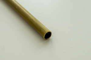 |
Brass Tube Diameter: 6mm Inside diameter: 5.1mm |
The freewheel bearings require a smooth and precise axis that is hard to manufacture with standard FDM 3D-printer. Therefore, we integrated a brass tube that fulfils these properties. Available, for example, at Conrad Electronics. |
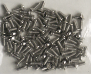 |
M2 Screws l=6mm |
M2 screws can be bought in different sizes at many local hardware stores. |
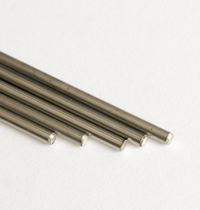 |
Round Bars Stainless steel, d=3.00mm |
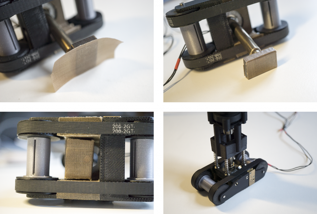
We used the round bars for two purposes: First, both axis of the rapid iron-on tool are made of round bars. In addition, we also use these round bars as guide rails for the spring-loaded mechanism. Therefore we cut the round bar into different pieces of required length with a metal saw and deburred the edges with metal files. Such metal round bars are available, for example, on Ebay. |
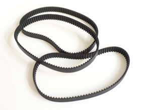 |
Timing Belts Teeth: GT2; Width: 6mm; Length: 200mm, closed |
The rapid iron-on tool based on the idea of using timing belts to synchronize the front and back axis. This is important since the iron-on tapes are made of a carrier layer that continuously moves between the axes. Available, for example, on Amazon. |
| 3D Model | Description |
|---|---|
 |
Wheel Axis Parts freewheel_bearing_parts.zip (recommended version with freewheels and bearings, compatible spool type: I-guide rail) wheel_bearing_parts.zip wheel_parts.zip |
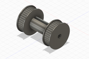
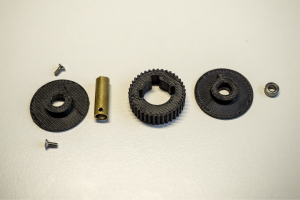
2.1 Axis Part Overview
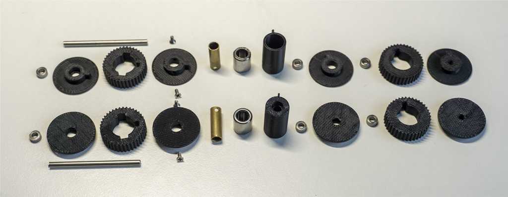
Both wheel axis are assembled by around 30 parts. The overview shows each part.
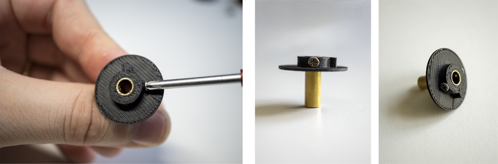
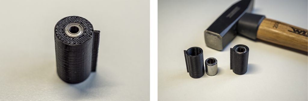
2.2 Brass Tube Wheel: Shaft Part (1/3)
- Cut and deburr the brass tube
- Place the brass tube into the 3D printed part.
(If necessary you can carefully use a hammer) - Drill two holes in the brass tube.
>(2mm holes, please align the tube first before drilling) - Fix the tube by using two screws.
(M2, l=6mm)
The brass tube wheel part consists of two outer wheel plates, a timing belt gear, the brass tube itself with two holes, as well as two M2 screws.
2.3 Brass Tube Wheel: Bearing Part (2/3)
- 3D-print the outer wheel plate
- Place the mini gear on top
- Carefully use a hammer to fit the gear into the 3D-printed part
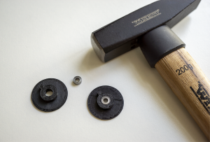
The mini bearing is carefully hammered into wheel cover. Please make sure to do not destroy the bearing by applying to much force.
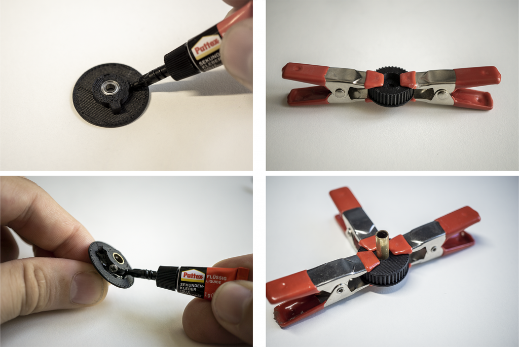
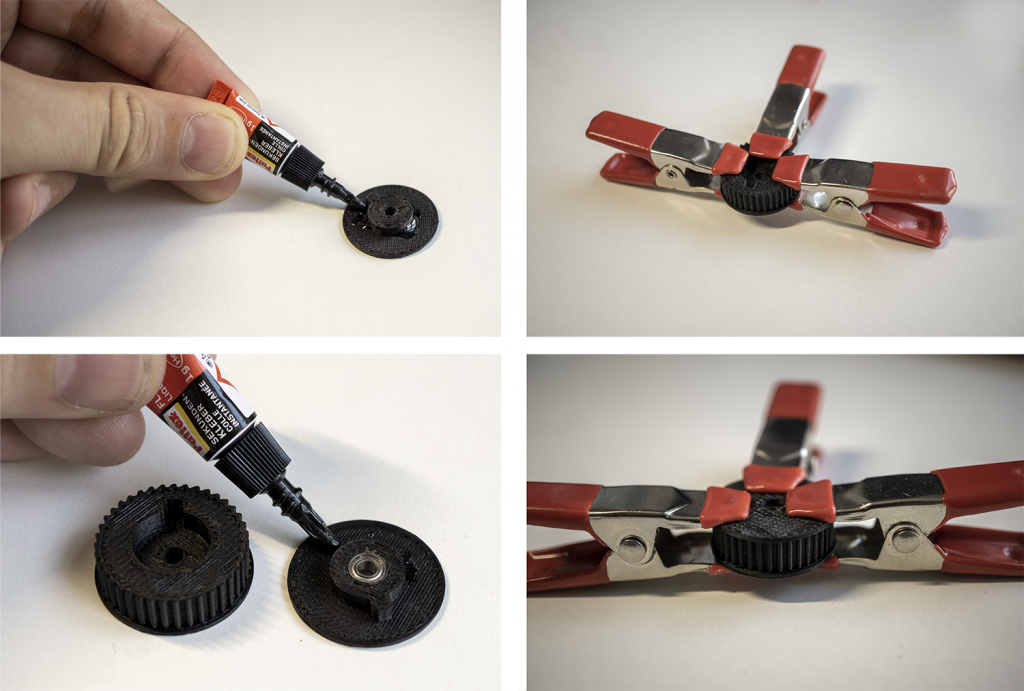
2.4 Brass Tube Wheel: Assembly (3/3)
- Glue all three parts
- Use mini clamps for ensuring good contact
- Make sure that a 3mm metal axis still fits and did not hit the screws
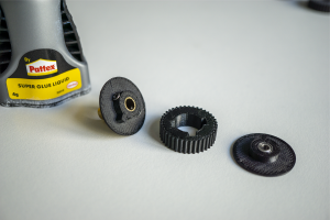
In order to complete the brass tube wheel you have to glue the shaft part (left), the gear part (middle) and the bearing part (right).
Assemble all parts using press fit. You can also use all-purpose glue to permanently connect all 3D-printed parts of the wheel axes together.
2.5 Opposite Basic Wheel
- Assembly all parts similar to the brass tube wheel
- Use one mini gear
- Use all-purpose glue
- Mini clamps can be used to ensure good connection
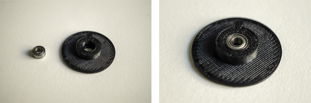
2.6 Freewheel Axis
- Place and gently press the freewheel bearing into the hole
- Use a hammer to completely press in the freewheel bearing
(please make sure that you do not destroy the gear by hammering with too much force. If you need more force use a rubber mallet or tweak the measures of your 3D-printed parts.) - Make sure that you consider the correct direction
(for one pair of axis you have to insert one freewheel bearing with the label to the top and one gear with the label to the bottom.) - Swap the axis and gently press mini gear in
- Use a hammer to completely press in the mini gear.
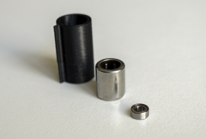
The freewheel axis is assembled by using three parts: the 3D-printed axis (left), the freewheel bearing (middle), and a mini bearing.
2.7 Axis Assembly
- Make sure that the basic wheels are connected via a timing belt and the brass tube wheels are connected via a timing belt.
(Both timing belts should move independently) - Check that the freewheel axes could be freely rotated in one direction (without moving the timing belt) to support a fast tightening of the iron-on spools.
(Each freewheel axis should move in another direction)
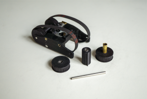
Every axis consist of three parts: a basic wheel (left), a freewheel axis (middle), and the tube brass wheel (right).
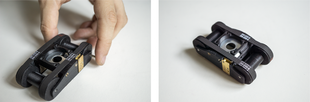
Finally, assemble the carriage model with the wheel axis by pushing the metal rods inside (left). The assembled model should nicely move (right). If the wheels stuck, please check the friction and proper fit of every involved part.
Step 3: Integration of the Actuated Cutting Blade
Required tools:
FDM 3D Printer, sandpaper (extra fine, 600 grit), fine-cut files, screwdriver (slotted), hacksaw (with metal saw blade), precision side cutter, tweezers, soldering iron (with soldering tin and grease), heat gun (with hook nozzle for shrinking tubing), wire stripper, diamond cutting disc (for cutting hardened steel).
3.1 Circuit Diagram
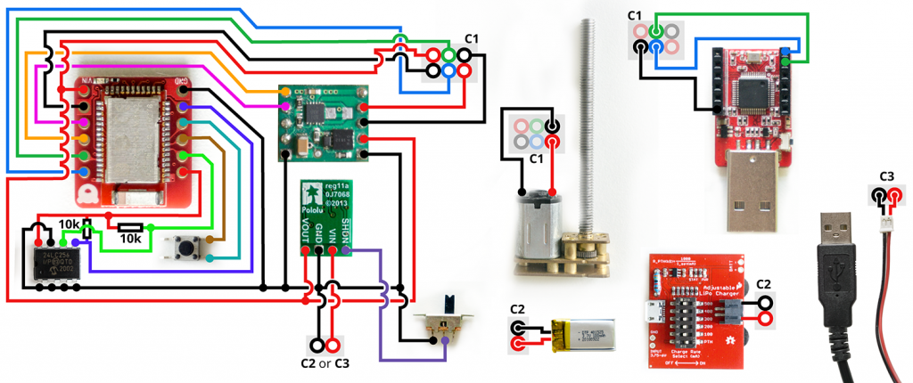
*While there is currently no easy-to-use Arduino library available that can access the flash memory of the Nordic nRF52832 SoC, we used an external EEPROM to save calibration data.
3.2 Custom Circuit Board
| Image | Part | Description |
|---|---|---|
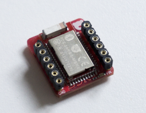 |
RedBear BLE Nano V2 nRF52832 SoC Bluetooth LE Arduino compatible |
We used the tiny Arduino compatible microcontroller RedBear BLE Nano V2 which based on the nRF52832 SoC. The built-in bluetooth capability allows us to easily configure calibration parameters wireless. While you can also use another micrcontroller (e.g., Arduino Nano 33 BLE), changes in the circuit design, controller housing and program code might be necessary. We ordered the RedBear BLE Nano V2 from Mouser. |
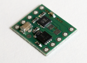 |
Single Brushed DC Motor Driver Carrier e.g., Pololu MAX14870 |
In order to control the actuated cutting blade, we need to control the DC motor. Therefore, we integrated the MAX14870 Single Brushed DC Motor Driver Carrier from Pololu that provides us a tiny H-bridge motor driver IC for speed and direction control. |
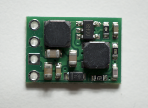 |
9V Step-Up/Step-Down Voltage Regulator S10V3F9 |
The 9V Step-Up/Step-Down Voltage Regulator takes an input voltage from 2.5V to 18V and increases or decreases the voltage to a fixed 9V output. We used this chip to increase the 5V USB or 3.7V LiPo battery to power the motor driver. Available, for example, at Pololu. |
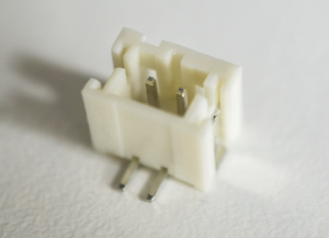 |
Angled JST-Connector 2 contacts, 2mm |
To power the motor control board, we used an angled JST-connector that fits most LiPo battery connectors. Available, for example, at Reichelt Elektronik. |
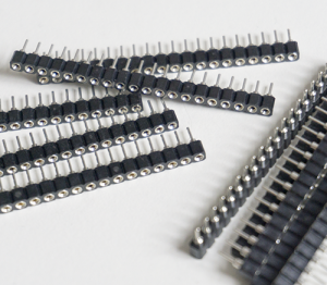 |
Female Pin Headers | We used small female pin headers for the prototyping and programming the electrical parts (e.g., microcontroller, motor driver). For the final assembly, we directly soldered all connections to the components in oder to save space. We used tiny female pin headers from Reichelt Electronics. |
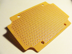 |
Prototyping PCB Phenolic paper 0.1″/2.54mm, 80mm x 52mm, 35µm |
We used these prototyping boards as a basis for our circuits. Available, for example, at Conrad Electronics. |
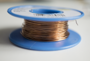 |
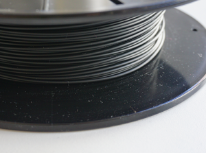
Enamelled copper wire d=0.30mm |
To save space, we used enamelled copper wire for the miniaturized version of the motor control circuit. Available, for example, at Conrad Electronics. |
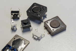 |
Push Button 6mm x 6mm |
In order to trigger the actuated cutting blade, we used a 6mm x 6mm tactile push button. Available, for example, at Mouser. |
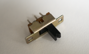 |
Miniature Slide Switch 19mm x 5.6mm x 5mm; Mounting holes 15mm |
We used a slide switch to activate or deactivate the power of the circuit. Available, for example, at DigiKey or Mouser Electronics. |
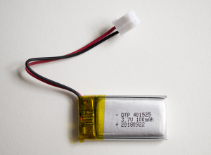 |
LiPo battery 25,5mm x 12,5mm x 6,2mm; 100mAh; 3,7V; JST-PH-Connector (2mm). |
In order to provide power to the microcontroller as well as the actuated motor, we integrated a small LiPo battery. If you need longer battery time, you can also choose a larger one or switch to USB power. Available, for example, at EXP-Tech. |
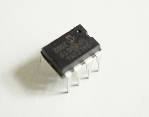 |
I²C EEPROM Microchip Technology 24LC256-I/P; EEPROM 256 kBit; 32K x 8 |
While there is currently no easy-to-use Arduino library available that can access the flash memory of the Nordic nRF52832 SoC, we used an external EEPROM to save calibration data. Available, for example, at Conrad Electronics. |
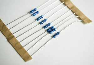 |
10k resistor Metal film resistor Axial lead 0.6W |
We used two 10k resistor to connect the external EEPROM (see circuit diagram). Available, for example, at Conrad Electronics. |
First, we recommend to test the circuit with pin connectors to ensure that every component works as expected and you did not have to change connections for the final circuit.Miniaturizing and soldering the circuit board
Next, the circuit needs to be miniaturized by placing and soldering all components on a prototyping PCB. To optimize spacings, we used enamelled copper wire, arrange some components above each other and break out the most important pins (programming interface, power, motor).
Test environment with pin connectors to check the functionality of the circuit and components.
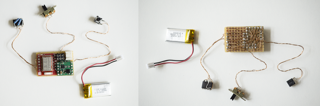
Miniaturized version of the circuit (left: top view; right: bottom view). The external DAPLink programmer is not shown since the programmer is not a part of the circuit and only required for initial programming.
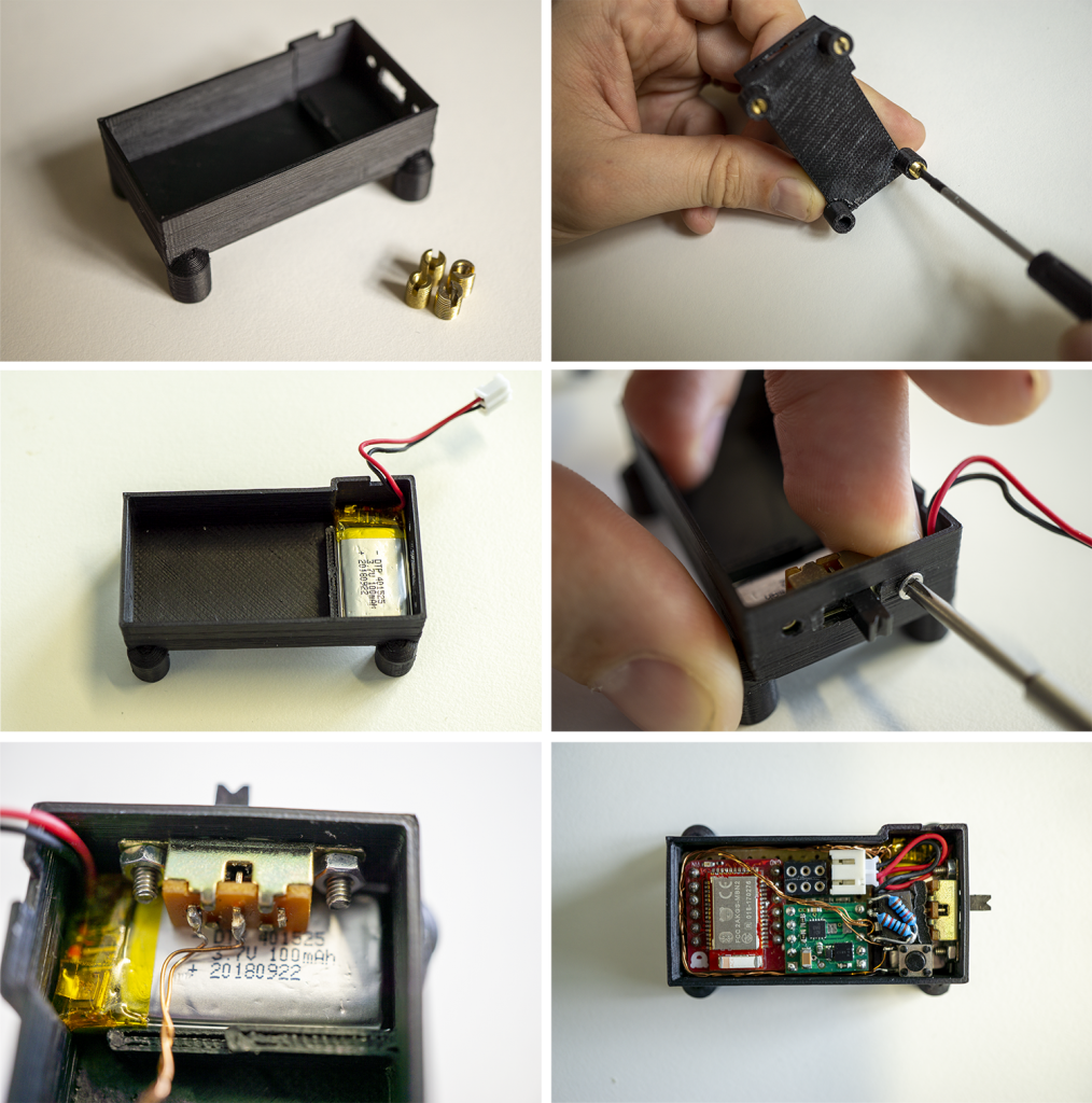
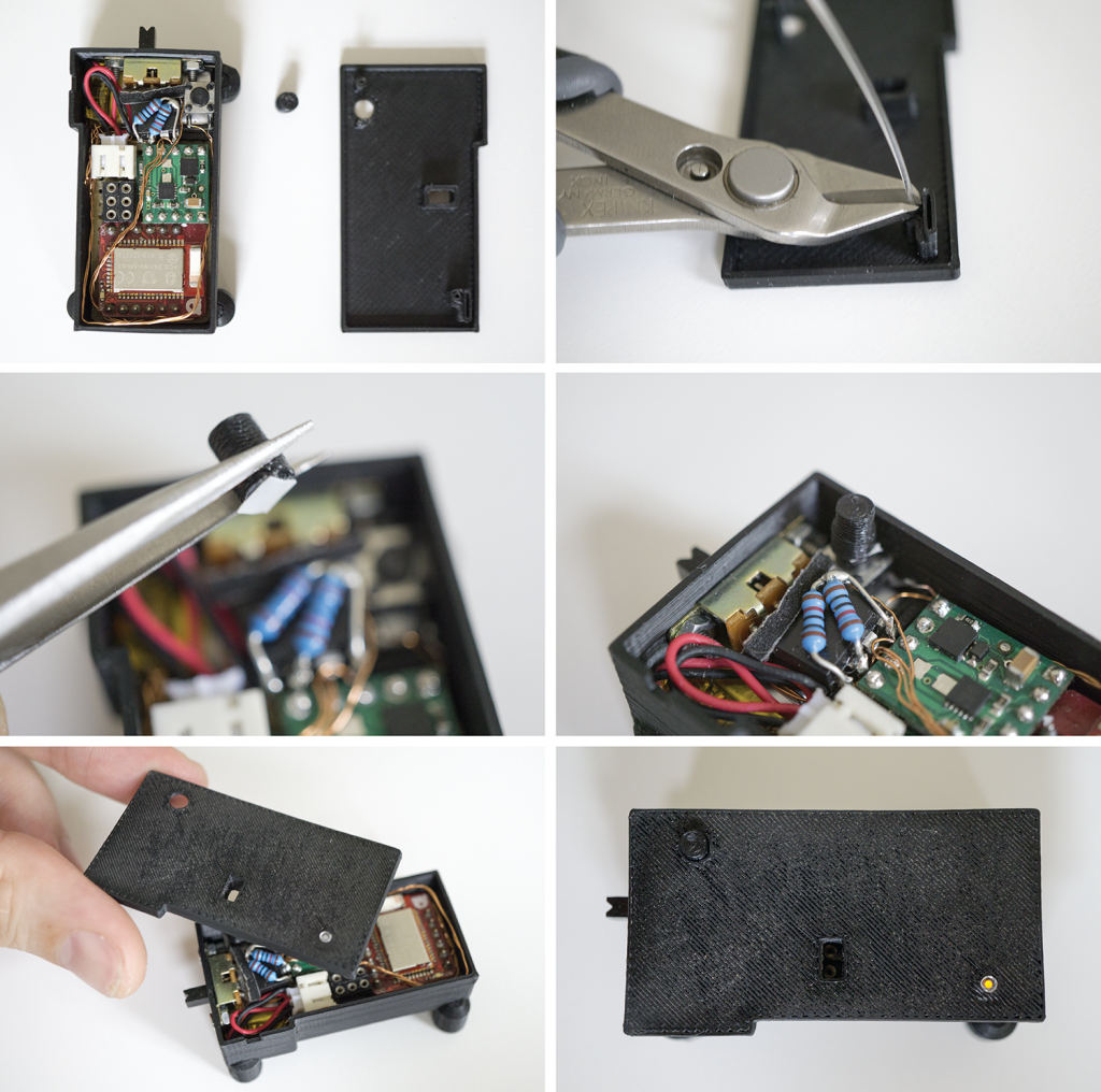
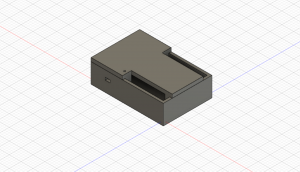
3.3 Housing
In the following, we build a housing for the electronics that can be seamlessly attached to the Rapid Iron-On Tool.
| Image | Part | Description |
|---|---|---|
|
3D-Printer Filament | We used black Tiertime UP Fila ABS to 3D-print a small housing for the custom motor control board. Of course you can also use any other filament. |
|
Threaded Inserts M2*0.4 / M4.5*0.5; 6mm; SKU: GS08040-01 |
We use threaded inserts to create reusable as well as strong screw connections between different 3D-printed parts (e.g., between the carriage and the spring-loaded iron) of the rapid iron-on tool. Available, for example, on Amazon. |
|
M2 Screws l=6mm |
We used two M2 screws with a length of 6mm to mount the SPDT slide switch to the 3D-printed housing. M2 screws can be bought in different sizes at many local hardware stores. |
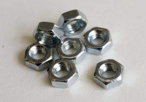 |
Nuts M2 |
We used two M2 nuts to tighten the screws that hold the SPDT slide switch in place. Nuts for metric screws can be bought in different sizes at many local hardware stores. |
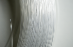 |
Optical fiber cable d=0.03″/0.75mm |
We used an optical fiber cable to make the built-in LEDs visible in the housing. Available, for example, at Amazon. |
| 3D Model | Description |
|---|---|
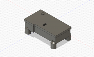 |
Motor Control Housing Motor_Control_Housing-Top.stl Motor_Control_Housing-Bottom.stl Motor_Control_Housing-Button.stl |
3.4 Programming
| Image | Part | Description |
|---|---|---|
|
3D-Printer Filament | We used black Tiertime UP Fila ABS to 3D-print a small housing for the DAPLink programmer. Of course you can also use any other filament. |
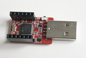 |
DAPLink Programmer e.g., RedBearLab DAPLink v1.5 |
The microcontroller did not have a built-in USB programming interface due to the space-saving form factor. Therefore, we used an external DAPLink Programmer that we just need for an initial programming since all calibration and control data can be accessed later via bluetooth. We used the RedBearLab DAPLink v1.5 that is part of the RedBearLab starter kit. We ordered the kit from Mouser. |
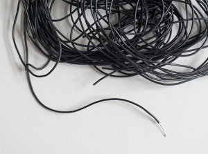 |
Highflex Cable 0.05mm²; PVC 0.8mm; 10×0.08mm |
Since we have no components that require high electrical load, we used thin and flexible standard stranded traces to connect all electrical components. Available, for example, at Conrad Electronics. |
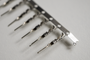 |
Male Crimp Pins for 0.1″ Housings |
We used male crimp contacts to fabricate cable that fit into the female pin sockets of the DAPLink programmer. Available, for example, at Pololu. |
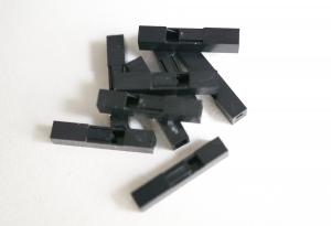 |
0.1″ Crimp Connector Housing: 1×1-Pin | In order to protect the male crimp contacts, we used standard crimp housings. Available, for example, at Pololu. |
 |
Heat Shrink Tubing d=1.20mm; ratio: 2:1 |
We used heat shrink tubings to insulate the jumper cable that we fabricated with the male pin headers and thin cables. |
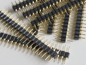 |
Male Pin Headers | To fabricate small jumper cables, we used tiny machine pins (swiss round pins). However, it is of course also possible to use standard ones. For example, available at Adafruit. |
|
Optical fiber cable d=0.03″/0.75mm |
We used an optical fiber cable to make the built-in LEDs visible in the housing. Available, for example, at Amazon. |
| 3D Model | Description |
|---|---|
 |
DAPLink Programmer Housing DAPLink_Housing-Top.stl DAPLink_Housing-Bottom.stl |
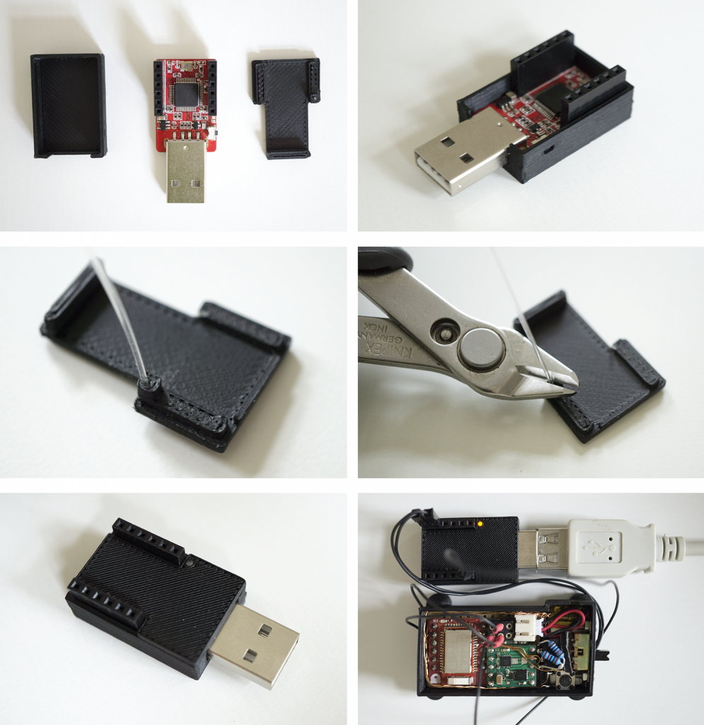
In order to program the controller you have to connect GND, SWCLK and SWDIO and power the board (e.g., by using the integrated LiPo-battery or USB power). For further connections details on how to connect the DAPLink programmer to the motor control board, please refer to the circuit diagram illustration.
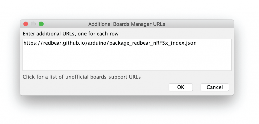
Setup Arduino IDE
In order to program the microcontroller, please install the latest version of the Arduino IDE. Furthermore, you have to:
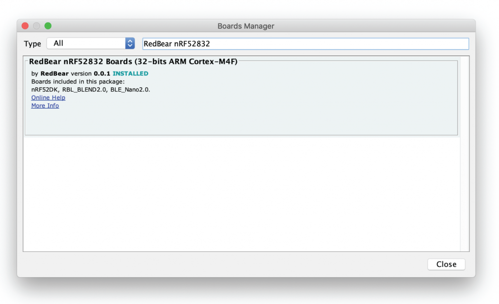
To use the BLE Nano V2 in Arduino, you have to add https://redbear.github.io/arduino/package_redbear_nRF5x_index.json to the additional Board Manager URL form and install the RedBear nRF52832 Boards (32-bits ARM Cortex-M4F) package via the Board Manager.
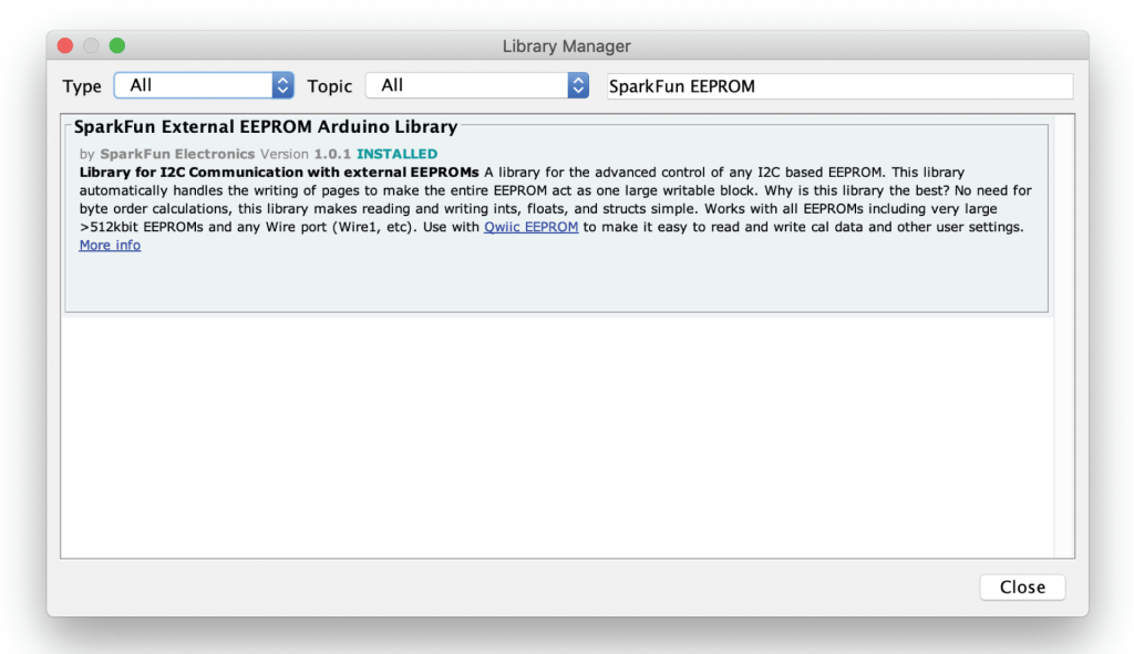
In addition, you have to install the SparkFun External EEPROM library. You can easily do that via the Arduino integrated library manager (just type in “SparkFun EEPROM”) or install it manually by downloading it from GitHub.
Arduino Sketch
/* Rapid Iron-on User Interfaces: Hands-on Fabrication of Interactive Textile Prototypes
   - Konstantin Klamka, Raimund Dachselt & Jürgen Steimle -

   Sketch for controlling the cutting blade:
   If a user hits the push button, a short
   motor motion sequence is initiated that
   moves the blade forth and back.

   created 2019 by
   Konstantin Klamka
   Interactive Media Lab Dresden, Germany

   This example code is in the public domain.

   Project website:
   http://www.imld.de/rio/

*/

// Includes
#include <nRF5x_BLE_API.h>
#include <SparkFun_External_EEPROM.h>

 // EEPROM
ExternalEEPROM myMem;

// Device Name
#define DEVICE_NAME       "RIO_Motor_Control"
#define DEVICE_NAME_SHORT "RIO"

// GATT Service and Characteristic Addresses
#define BLE_GATT_RIO_CONTROL_SERVICE       0x713D
#define BLE_GATT_CHAR_ADDR_MOTOR_CONTROL   0x703A
#define BLE_GATT_CHAR_ADDR_MOTOR_SPEED     0x703B
#define BLE_GATT_CHAR_ADDR_CUT_TIME_OUT    0x703C
#define BLE_GATT_CHAR_ADDR_CUT_TIME_IN     0x703D
#define BLE_GATT_CHAR_ADDR_BLADE_TRIGGER   0x703E
#define BLE_GATT_CHAR_ADDR_MOTOR_DIRECTION 0x703F
#define TXRX_BUF_LEN                       20

// Pin Mapping
const int buttonPin1 = 0;
const int buttonPin2 = 1;
const int motorPwmPin = 4;
const int motorDirPin = 5;
const int ledPin = 13;

// Global State Varaibles
int16_t cuttingTimeOut = 2200;
int16_t cuttingTimeIn = 2200;
int16_t motorSpeed = 255;
int16_t motorDirectionOut = 255;
int16_t motorDirectionIn = 0;
int16_t motorDirection = 0;

int currentButtonState = 0;  // current state of the button
int lastButtonState = 1;     // previous state of the button
Ticker buttonCheckerTicker;

// BLE
BLE ble;
GattCharacteristic characteristicMotorControl(BLE_GATT_CHAR_ADDR_MOTOR_CONTROL, 0, 1, TXRX_BUF_LEN, GattCharacteristic::BLE_GATT_CHAR_PROPERTIES_WRITE |  GattCharacteristic::BLE_GATT_CHAR_PROPERTIES_READ| GattCharacteristic::BLE_GATT_CHAR_PROPERTIES_WRITE_WITHOUT_RESPONSE);
GattCharacteristic characteristicMotorSpeed(BLE_GATT_CHAR_ADDR_MOTOR_SPEED, 0, 1, TXRX_BUF_LEN, GattCharacteristic::BLE_GATT_CHAR_PROPERTIES_WRITE | GattCharacteristic::BLE_GATT_CHAR_PROPERTIES_READ| GattCharacteristic::BLE_GATT_CHAR_PROPERTIES_WRITE_WITHOUT_RESPONSE);
GattCharacteristic characteristicCuttingTimeOut(BLE_GATT_CHAR_ADDR_CUT_TIME_OUT, 0, 1, TXRX_BUF_LEN, GattCharacteristic::BLE_GATT_CHAR_PROPERTIES_WRITE | GattCharacteristic::BLE_GATT_CHAR_PROPERTIES_READ| GattCharacteristic::BLE_GATT_CHAR_PROPERTIES_WRITE_WITHOUT_RESPONSE);
GattCharacteristic characteristicCuttingTimeIn(BLE_GATT_CHAR_ADDR_CUT_TIME_IN, 0, 1, TXRX_BUF_LEN, GattCharacteristic::BLE_GATT_CHAR_PROPERTIES_WRITE | GattCharacteristic::BLE_GATT_CHAR_PROPERTIES_READ| GattCharacteristic::BLE_GATT_CHAR_PROPERTIES_WRITE_WITHOUT_RESPONSE);
GattCharacteristic characteristicBladeTrigger(BLE_GATT_CHAR_ADDR_BLADE_TRIGGER, 0, 1, TXRX_BUF_LEN, GattCharacteristic::BLE_GATT_CHAR_PROPERTIES_WRITE | GattCharacteristic::BLE_GATT_CHAR_PROPERTIES_READ| GattCharacteristic::BLE_GATT_CHAR_PROPERTIES_WRITE_WITHOUT_RESPONSE);
GattCharacteristic characteristicMotorDirection(BLE_GATT_CHAR_ADDR_MOTOR_DIRECTION, 0, 1, TXRX_BUF_LEN, GattCharacteristic::BLE_GATT_CHAR_PROPERTIES_WRITE | GattCharacteristic::BLE_GATT_CHAR_PROPERTIES_READ| GattCharacteristic::BLE_GATT_CHAR_PROPERTIES_WRITE_WITHOUT_RESPONSE);
GattCharacteristic *uartChars[] = {&characteristicMotorControl, &characteristicMotorSpeed, &characteristicCuttingTimeOut, &characteristicCuttingTimeIn, &characteristicBladeTrigger, &characteristicMotorDirection};
GattService        uartService(BLE_GATT_RIO_CONTROL_SERVICE, uartChars, sizeof(uartChars) / sizeof(GattCharacteristic *));

// Setup
void setup() {

  // Pin configuration
  pinMode(buttonPin1, INPUT_PULLUP);
  pinMode(buttonPin2, OUTPUT);
  pinMode(ledPin, OUTPUT);
  analogWrite(motorPwmPin, 0);
  digitalWrite(buttonPin2, LOW);

  // BLE
  ble.init();
  ble.onDataWritten(gattServerWriteCallBack);
  ble.onDisconnection(disconnectionCallBack);
  setAdvertisement();
  ble.setAdvertisingType(GapAdvertisingParams::ADV_CONNECTABLE_UNDIRECTED);
  ble.addService(uartService);
  ble.setDeviceName((const uint8_t *)DEVICE_NAME);
  ble.setTxPower(4);
  ble.setAdvertisingInterval(160);
  ble.setAdvertisingTimeout(0);
  ble.startAdvertising();

  if (motorDirection == 0) {
      motorDirectionOut = 255;
      motorDirectionIn = 0;
    }
    else{
      motorDirectionOut = 0;
      motorDirectionIn = 255;
    }

  // Attach ticker for checking the trigger button state...
  buttonCheckerTicker.attach(checkTriggerButtonState, 0.1);

  Wire.begin();
  myMem.begin();
  if (myMem.begin()){loadCalibrationDataFromEEPROM();}
  delay(100);
  updateAllFromCurrentStateBLECharacteristic();
}

// Loop
void loop() {
  ble.waitForEvent();
}

void checkTriggerButtonState(void) {
  currentButtonState = digitalRead(buttonPin1);
  if (currentButtonState != lastButtonState) {
    if (currentButtonState == HIGH) {executeCut();}
    delay(50);
  }
  lastButtonState = currentButtonState;
}

void executeCut() {
  digitalWrite(ledPin, HIGH);
  analogWrite(motorDirPin, motorDirectionOut);
  analogWrite(motorPwmPin, motorSpeed);
  delay(cuttingTimeOut);
  analogWrite(motorDirPin, motorDirectionIn);
  delay(cuttingTimeIn);
  analogWrite(motorPwmPin, 0);
  digitalWrite(ledPin, LOW);
}

void gattServerWriteCallBack(const GattWriteCallbackParams *Handler) {

  // Live Motor Control
  // ---------------
  if (Handler->handle == characteristicMotorControl.getValueAttribute().getHandle()) {
    int characteristicIntValue = getCharacteristicValue(Handler);

    digitalWrite(ledPin, HIGH);
    if (characteristicIntValue > 0) {
      analogWrite(motorDirPin, motorDirectionOut);
      analogWrite(motorPwmPin, motorSpeed);
      delay(characteristicIntValue);
    }
    else
    {
      analogWrite(motorDirPin, motorDirectionIn);
      analogWrite(motorPwmPin, motorSpeed);
      delay(abs(characteristicIntValue));
    }
    analogWrite(motorPwmPin, 0);
    digitalWrite(ledPin, LOW);
  }

  // Motor Speed
  // ---------------
  else if (Handler->handle == characteristicMotorSpeed.getValueAttribute().getHandle()) {
    int characteristicIntValue = getCharacteristicValue(Handler);
    if (characteristicIntValue >= 255) {motorSpeed = 255;}
    else if (characteristicIntValue <= 0) {motorSpeed = 0;}
    else {motorSpeed = characteristicIntValue;}
    static uint8_t value_buffer[20];
    sprintf((char*)value_buffer, "%u", motorSpeed);
    ble.updateCharacteristicValue(characteristicMotorSpeed.getValueAttribute().getHandle(), (const uint8_t*)value_buffer, strlen((const char*)value_buffer));

  }


  // Cutting Time Out
  // ---------------
  else if (Handler->handle == characteristicCuttingTimeOut.getValueAttribute().getHandle()) {
    int characteristicIntValue = getCharacteristicValue(Handler);
    if (characteristicIntValue <= 0) {cuttingTimeOut = 0;}
    else {cuttingTimeOut = characteristicIntValue;}
    static uint8_t value_buffer[20];
    sprintf((char*)value_buffer, "%u", cuttingTimeOut);
    ble.updateCharacteristicValue(characteristicCuttingTimeOut.getValueAttribute().getHandle(), (const uint8_t*)value_buffer, strlen((const char*)value_buffer));
  }

  // Cutting Time In
  // ---------------
  else if (Handler->handle == characteristicCuttingTimeIn.getValueAttribute().getHandle()) {
    int characteristicIntValue = getCharacteristicValue(Handler);
    if (characteristicIntValue <= 0) {cuttingTimeIn = 0;}
    else {cuttingTimeIn = characteristicIntValue;}
    static uint8_t value_buffer[20];
    sprintf((char*)value_buffer, "%u", cuttingTimeIn);
    ble.updateCharacteristicValue(characteristicCuttingTimeIn.getValueAttribute().getHandle(), (const uint8_t*)value_buffer, strlen((const char*)value_buffer));
  }

  // Cutting Trigger
  // ---------------
  else if (Handler->handle == characteristicBladeTrigger.getValueAttribute().getHandle()) {
    if (getCharacteristicValue(Handler) == 1) {executeCut();}
  }

  // Motor Direction
  // ---------------
  else if (Handler->handle == characteristicMotorDirection.getValueAttribute().getHandle()) {
    if (getCharacteristicValue(Handler) == 0) {
      motorDirection = 0;
      motorDirectionOut = 255;
      motorDirectionIn = 0;
      static uint8_t value_buffer[20];
      sprintf((char*)value_buffer, "%u", motorDirection);
      ble.updateCharacteristicValue(characteristicMotorDirection.getValueAttribute().getHandle(), (const uint8_t*)value_buffer, strlen((const char*)value_buffer));
    }
    else{
      motorDirection = 1;
      motorDirectionOut = 0;
      motorDirectionIn = 255;
      static uint8_t value_buffer[20];
      sprintf((char*)value_buffer, "%u", motorDirection);
      ble.updateCharacteristicValue(characteristicMotorDirection.getValueAttribute().getHandle(), (const uint8_t*)value_buffer, strlen((const char*)value_buffer));

    }
  }

  saveAllCalibrationData();
}

void setAdvertisement(void) {
  ble.accumulateAdvertisingPayload(GapAdvertisingData::BREDR_NOT_SUPPORTED | GapAdvertisingData::LE_GENERAL_DISCOVERABLE);
  ble.accumulateAdvertisingPayload(GapAdvertisingData::SHORTENED_LOCAL_NAME, (const uint8_t *)DEVICE_NAME_SHORT, sizeof(DEVICE_NAME_SHORT) - 1);
  ble.accumulateScanResponse(GapAdvertisingData::COMPLETE_LOCAL_NAME, (const uint8_t *)DEVICE_NAME, sizeof(DEVICE_NAME) - 1);
}

void disconnectionCallBack(const Gap::DisconnectionCallbackParams_t *params) {
  ble.startAdvertising();
}

int getCharacteristicValue(const GattWriteCallbackParams *Handler) {
  String characteristicStringValue;
  for (int index = 0; index < Handler->len; index++) {
    characteristicStringValue.concat((char)Handler->data[index]);
  }
  return characteristicStringValue.toInt();
}

void saveAllCalibrationData(){

// cuttingTimeOut
myMem.write(0, highByte(cuttingTimeOut));
myMem.write(1, lowByte(cuttingTimeOut));

// cuttingTimeIn
myMem.write(2, highByte(cuttingTimeIn));
myMem.write(3, lowByte(cuttingTimeIn));

// motorSpeed
myMem.write(4, highByte(motorSpeed));
myMem.write(5, lowByte(motorSpeed));

// motorDirection
myMem.write(6, highByte(motorDirection));
myMem.write(7, lowByte(motorDirection));

}

void loadCalibrationDataFromEEPROM(){
  cuttingTimeOut = ((byte)myMem.read(0) << 8) + myMem.read(1);
  cuttingTimeIn = ((byte)myMem.read(2) << 8) + myMem.read(3);
  motorSpeed = ((byte)myMem.read(4) << 8) + myMem.read(5);
  motorDirection = ((byte)myMem.read(6) << 8) + myMem.read(7);
}
 void updateAllFromCurrentStateBLECharacteristic(){
    static uint8_t value_buffer[20];
    sprintf((char*)value_buffer, "%u", motorSpeed);
    ble.updateCharacteristicValue(characteristicMotorSpeed.getValueAttribute().getHandle(), (const uint8_t*)value_buffer, strlen((const char*)value_buffer));
    sprintf((char*)value_buffer, "%u", cuttingTimeOut);
    ble.updateCharacteristicValue(characteristicCuttingTimeOut.getValueAttribute().getHandle(), (const uint8_t*)value_buffer, strlen((const char*)value_buffer));
    sprintf((char*)value_buffer, "%u", cuttingTimeIn);
    ble.updateCharacteristicValue(characteristicCuttingTimeIn.getValueAttribute().getHandle(), (const uint8_t*)value_buffer, strlen((const char*)value_buffer));
    sprintf((char*)value_buffer, "%u", motorDirection);
    ble.updateCharacteristicValue(characteristicMotorDirection.getValueAttribute().getHandle(), (const uint8_t*)value_buffer, strlen((const char*)value_buffer));
}
Download the sketch here: RIO_Motor_Control.ino
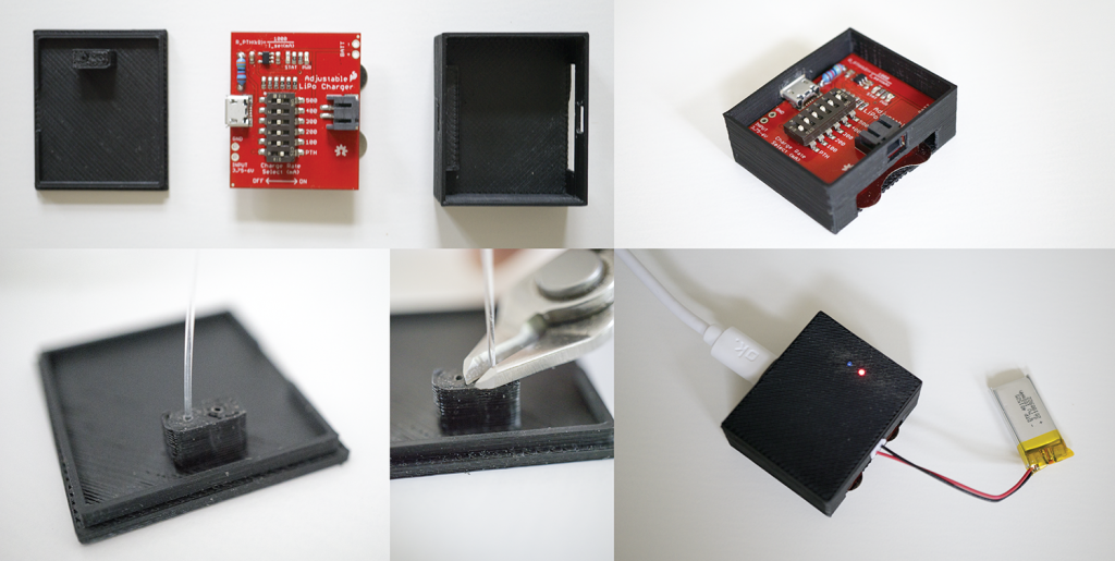
3.5 Powering & Charging
The circuit and the motor could be either powered by the built-in battery or by an external USB cable. In the following, we show how we realized a LiPo Charger Module for the rapid iron motor control as well as present the USB cable as an alternative power option.
LiPo Charger Module
| Image | Part | Description |
|---|---|---|
|
3D-Printer Filament | We used black Tiertime UP Fila ABS to 3D-print a small housing for the LiPo charger module. Of course you can also use any other filament. |
|
Optical fiber cable d=0.03″/0.75mm |
We used an optical fiber cable to make the built-in LEDs visible in the housing. Available, for example, at Amazon. |
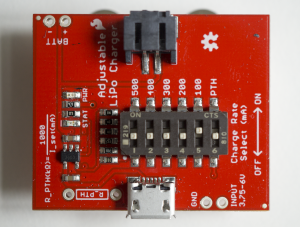 |
Adjustable LiPo Charger Max. charging current 30mA |
We used an adjustable LiPo charger from SparkFun which could be limited to a maximal charging current of 30mA by soldering a 34kOhm resistor on the board and activating the PTH mode. Available, for example, at SparkFun. |
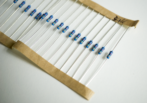 |
34k Resistor Metal film resistor Axial lead 0.6W |
We used this resistor to limit the maximal charging current to 30mA. Available, for example, at Reichelt Elektronik. |
|
LiPo battery 25,5mm x 12,5mm x 6,2mm; 100mAh; 3,7V; JST-PH-Connector (2mm). |
In order to provide power to the microcontroller as well as the actuated motor, we integrated a small LiPo battery. If you need longer battery time, you can also choose a larger one or switch to USB power. Available, for example, at EXP-Tech. |
| 3D Model | Description |
|---|---|
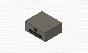 |
LiPo Charger Housing LiPo_Charging_Housing-Top.stl LiPo_Charging_Housing-Bottom.stl |
Since our 100mAh LiPo battery has a maximum charging current of 30mA, we have to limit the LiPo chargers output current. While the charge rate controller sets the maximum charge current with a resistor, we calculate the resistor based on the following formula:
R_PTH (kΩ) = 1000V / I_set (mA)
Therefore, we solder a 34k resistor on the board to limit the charging current to approx. 30mA and select the PTH mode by moving the DIP switch labeled “PTH” to the ON position.
USB Power
If you want to use 5V USB power instead the LiPo battery that we placed in the motor control unit, you can do this quite easily. Therefore, we just had to solder a USB to 2-Pin JST connector. This is possible due to the fact that the motor controller board uses a voltage regulator.
| Image | Part | Description |
|---|---|---|
|
3D-Printer Filament | We used black Tiertime UP Fila ABS to 3D-print a small housing that covers the connections between the USB cable and the JST connector. Of course you can also use any other filament. |
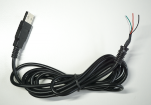 |
USB 2.0 cable Type A; open contacts |
If you want to realize the actuated blade without a battery, it is possible to use the 5V of a standard USB cable. Therefore, we used a type A cable with open contacts and soldered a 2-Pin JST connector to it to make it compatible to our motor control circuit as an battery replacement. Available, for example, at Reichelt Elektronik. |
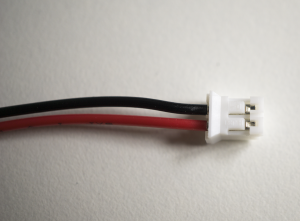 |
JST 2-pin cable 2mm |
In order to avoid additional connectors and seamlessly integrate a power option from USB for the motor driver board, we used a JST 2-pin connector as an alternative for the LiPo battery. Available, for example, at Adafruit. |
| 3D Model | Description |
|---|---|
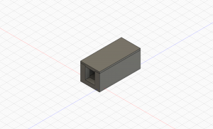 |
USB to 2-Pin JST Housing USB_to_2-Pin_JST_Housing-Bottom.stl USB_to_2-Pin_JST_Housing-Top.stl |
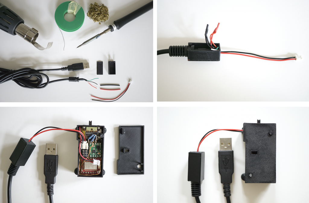
In order to power the motor control unit with USB power, you can solder a USB to JST adapter. We further 3D-print a small case to house the soldered contacts in a save way.
3.6 Linear Actuator
| Image | Part | Description |
|---|---|---|
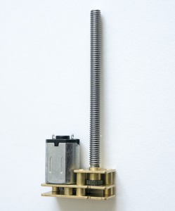 |
Micro Metal DC Motor with Gearbox N20 motor; M4 x 55mm wave; 6V; 1000RPM; SKU: GS06340-06 |
We used this one from Amazon |
|
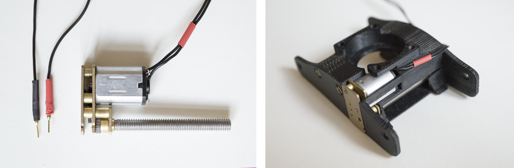
Highflex Cable 0.05mm²; PVC 0.8mm; 10×0.08mm |
Since we have no components that require high electrical load, we used thin and flexible standard stranded traces to connect all electrical components. Available, for example, at Conrad Electronics. |
|
Heat Shrink Tubing d=1.20mm; ratio: 2:1 |
We used heat shrink tubings to insulate the jumper cable that we fabricated with the male pin headers and thin cables. |
|
Male Pin Headers | To attach small jumper pins to the motor, we used tiny machine pins (swiss round pins). However, it is of course also possible to use standard ones. For example, available at Adafruit. |
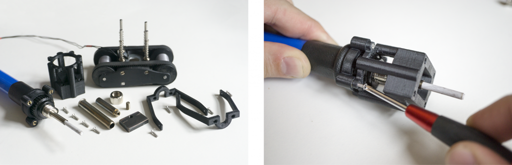
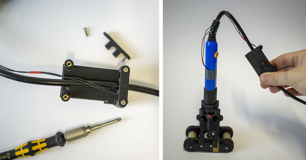
In order to place the linear actuator in the rapid iron-on tool, it is necessary to slightly modify the linear actuator by cutting off two parts with a hacksaw.Solder cables and connectors
Next, we solder two cables to the motor and male pins connectors. We used coloured heat shrink tubings to isolate as well as visually label the positive (red) and negative (black) contact of the motor.
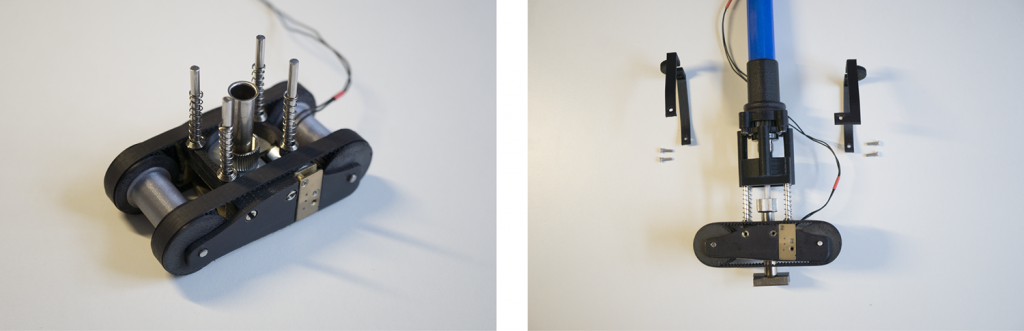
Physical installation test
Finally, we check whether the linear actuator fits into the carriage model.
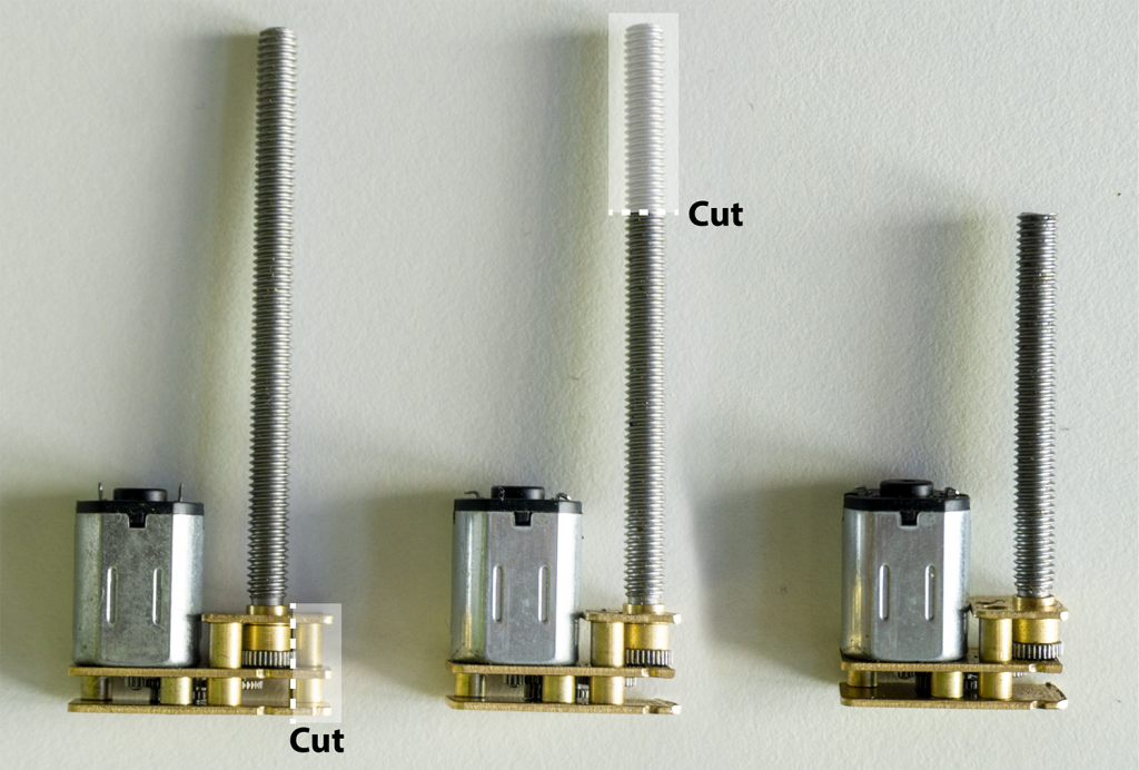
To prepare the motor for the installation in the carriage model you have to reduce the housing size and screw length.
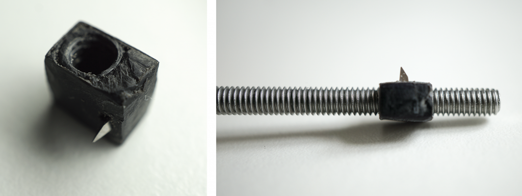
3.7 Cutting Blade Carrier
| Image | Part | Description |
|---|---|---|
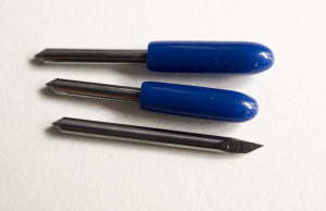 |
Cutting Blades |
| 3D Model | Description |
|---|---|
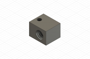 |
Cutting Blade Carrier Cutting_Blade_Carrier_1.75.stl |
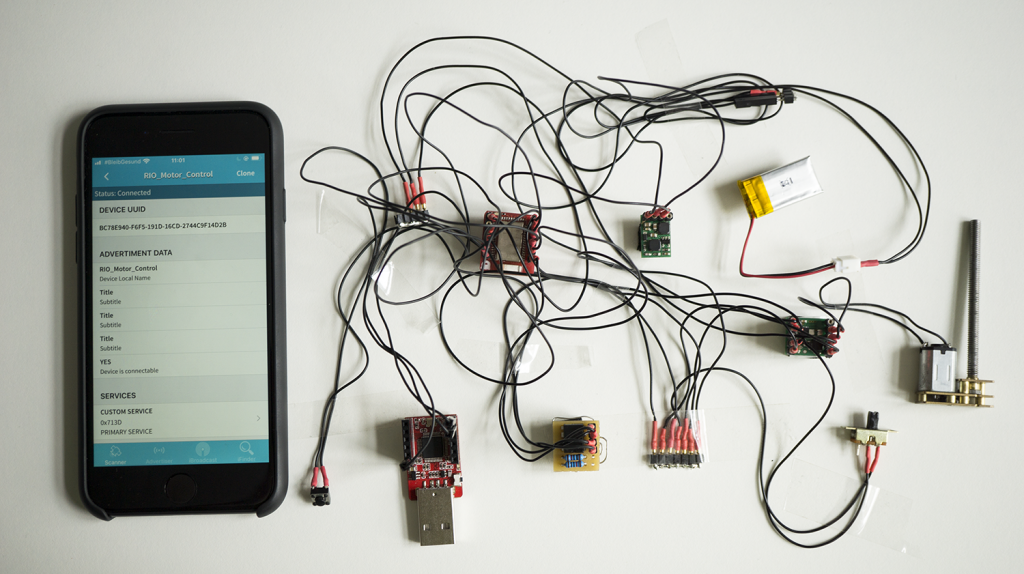
3.8 Create a Bluetooth Connection
In order to physically install and calibrate the actuated cutting blade, we need to establish a Bluetooth connection in order to access the Bluetooth Low Energy GATT calibration parameters.
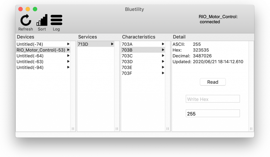
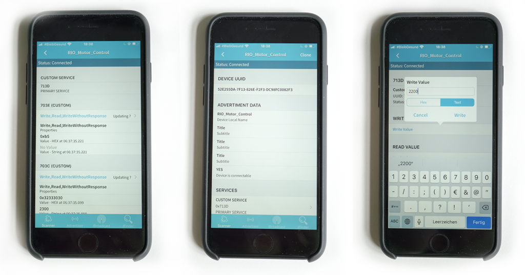
3.9 Calibration Command Overview
Please connect to the device RIO_Motor_Control and select the service 0x713D. In the following you can use the following commands:
| GATT Characteristic | Description |
|---|---|
| 0x703A | Motor Live Control This characteristic gives you full motion control of the actuated cutting blade. To move the blade you just have to change the ASCII value. Please note that the motion is immediately triggered. Parameters: Examples: |
| 0x703B | Motor Speed This characteristic defines the speed of the actuated cutting blade. To set the speed you just have to change the ASCII value. Please note that the change is immediately saved and applied to the next actuation. Parameters: Examples: |
| 0x703C | Cut Time (Out) This characteristic defines the time in milliseconds that the actuated cutting blade moves out when a user pushes the trigger button. To set the time you just have to change the ASCII value. Please note that the change is immediately saved and applied to the next actuation. Parameters: Examples: |
| 0x703D | Cut Time (In) This characteristic defines the time in milliseconds that the actuated cutting blade moves in when a user pushes the trigger button. To set the time you just have to change the ASCII value. Please note that the change is immediately saved and applied to the next actuation. Parameters: Examples: |
| 0x703E | Blade Trigger This characteristic remotely triggers a cutting action. To initiate a cutting process you just have to change the ASCII value. Please note that the change immediately triggers the blade. Parameters: Examples: |
| 0x703F | Motor Direction This characteristic allows you to swap the direction of in and out or in other words the polarity. Parameters: Examples: |
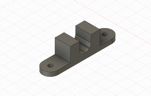
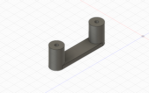
Step 4: Setup of the spring-loaded Mechanism
Required tools:
FDM 3D Printer, sandpaper (extra fine, 600 grit), fine-cut files, hacksaw (with metal saw blade), rubber mallet.
| Image | Part | Description |
|---|---|---|
|
High-temperature ABS Filament Print temperature: 270°C |
ABS can be mechanized, polished, sanded, drilled and glued and the finish is still good. In addition, it is extremely strong, more heat-resistant and it has certain flexibility. All of which makes it the perfect material for the rapid iron-on tool. We used Tiertime UP Fila ABS. |
|
Round Bars Stainless steel, d=3.00mm |
We used the round bars for two purposes: First, both axis of the rapid iron-on tool are made of round bars. In addition, we also use these round bars as guide rails for the spring-loaded mechanism. Therefore we cut the round bar into different pieces of required length with a metal saw and deburred the edges with metal files. Such metal round bars are available, for example, on Ebay. |
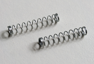 |
Springs from ballpoint pens; approx. d=4.2mm; l=25mm |
We upcycled small springs from old ballpoint pens. We paid attention that the springs nicely fit above the round bars that we used. In addition, the springs should be approximately equal in their length (25mm) and spring constant to ensure a nice motion. |
| 3D Model | Description |
|---|---|
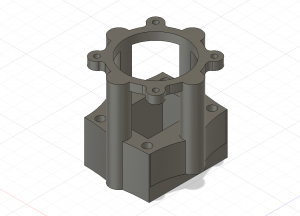 |
Connector Carriage ConnectorCarriage.stl |
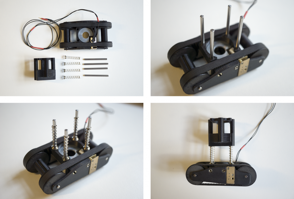
Cut the metal axes to the desired length (46mm). Assemble the metal axes with the carriage model and put over the springs.
Step 5: Integration of the Iron Adapter
Required tools:
FDM 3D Printer, sandpaper (extra fine, 600 grit), screwdriver (slotted).
| Image | Part | Description |
|---|---|---|
|
High-temperature ABS Filament Print temperature: 270°C |
ABS can be mechanized, polished, sanded, drilled and glued and the finish is still good. In addition, it is extremely strong, more heat-resistant and it has certain flexibility. All of which makes it the perfect material for the rapid iron-on tool. We used Tiertime UP Fila ABS. |
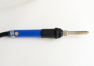 |
Soldering Iron temperature adjustable, with soldering tips that are screwable (M4) |
As a main heat generating component, we utilized a temperature-adjustable soldering iron with a tip that is screwable (M4). This connection allows us to mount own custom ironing plates. In detail, we build on this one from Amazon. |
|
Threaded Inserts M2*0.4 / M4.5*0.5; 6mm; SKU: GS08040-01 |
We use threaded inserts to create reusable as well as strong screw connections between different 3D-printed parts (e.g., between the carriage and the spring-loaded iron) of the rapid iron-on tool. Available, for example, on Amazon. |
| 3D Model | Description |
|---|---|
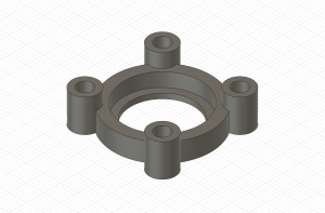 |
Iron Connector IronConnector.stlIronConnector_cable_guidance.stl (extended version with a small clip to guide the motor cables) |
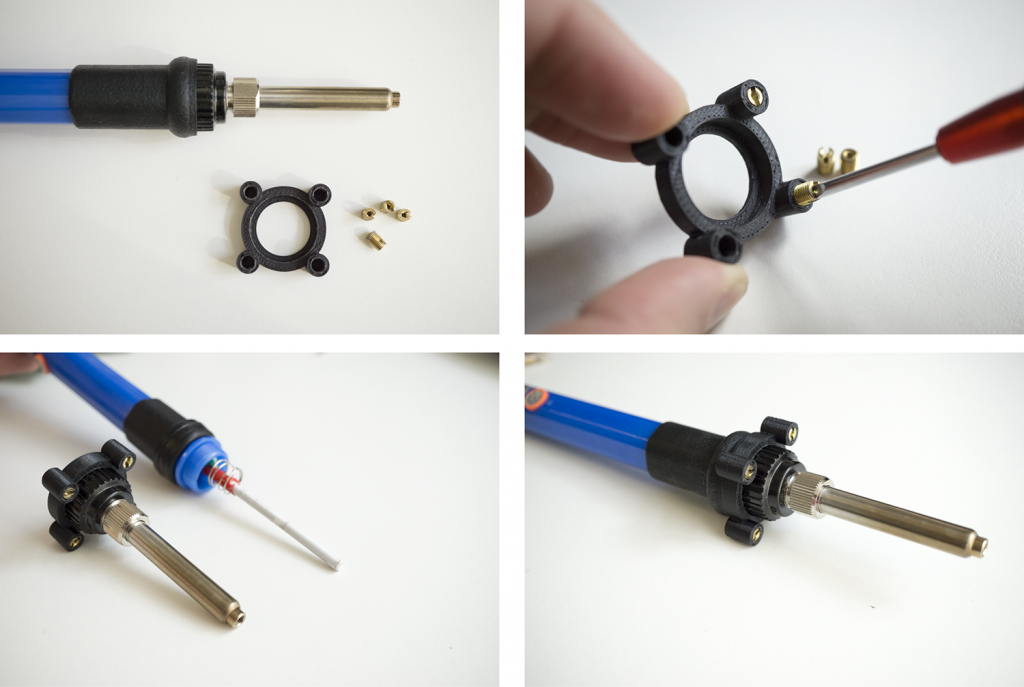
Screw in the four threaded inserts in the iron connector part. Unscrew the lower part of the soldering iron, place the iron connector and assemble the iron again.
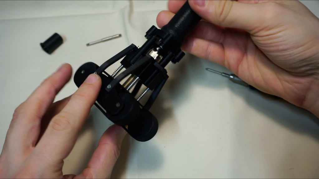
Step 6: Assembly of the spring-loaded Carriage and Iron
Required tools:
Screwdriver (cross-head), hacksaw (with metal saw blade), scissor and hobby knife, bench drilling machine, thread cutter M4.
| Image | Part | Description |
|---|---|---|
|
M2 Screws in different lengths |
The M2 screws fit into the threaded inserts and allow us to strongly screw different parts together. M2 screws can be bought in different sizes at many local hardware stores. |
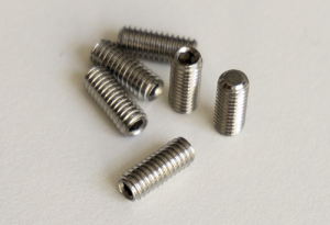 |
Grub Screws stainless steel, M4x10mm, DIN 913 |
We used a grub screw to connect our custom-made, exchangeable irons with the soldering iron. It might be necessary to shorten and grind the screws to perfectly fit into the setup. Available, for example, on Ebay. |
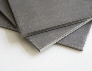 |
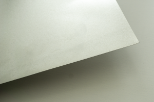
Steel Sheets S235, thickness: 4mm |
The steel sheets serve us as a base material to create the exchangeable irons for the rapid iron-on tool. Therefore, we cut out some small plates with a metal saw, drill a hole and finally use a thread cutter with cutting oil to realize a M4 screw thread. Such metal sheets are available, for example, on Ebay. |
|
Glass Fabric Tape PTFE, 25mm x 10m, heat resistant up to 260°C, self-adhesive |
The bonding iron is very hot and in close proximity to the spring-loaded carriage. To add an additional protection layer for accidentally physical contacts of the iron, we partly add glass fabric tape made of polytetrafluoroethylene that is able to temporarily resist heat. For our current prototype, we used this one from Amazon. |
Connect the carriage model with the previously assembled iron connector by using four screws.
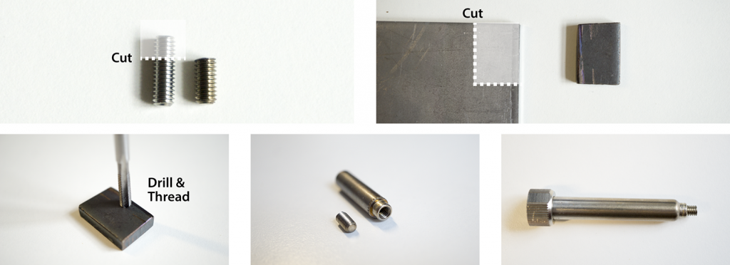
Saw out an iron plate (18mm x 22.8mm) of a steel sheet (thickness 4mm). Drill a hole in the iron plate. Cut a thread (size: M4) in the hole.
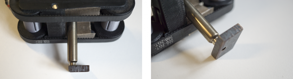
Screw the iron plate tight to the soldering iron screw tip.
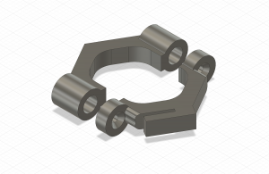
Step 7: Assembly of the Brackets and Motor Control Unit
Required tools:
Screwdriver (cross-head).
7.1 Assembly of the Brackets
| Image | Part | Description |
|---|---|---|
|
High-temperature ABS Filament Print temperature: 270°C |
ABS can be mechanized, polished, sanded, drilled and glued and the finish is still good. In addition, it is extremely strong, more heat-resistant and it has certain flexibility. All of which makes it the perfect material for the rapid iron-on tool. We used Tiertime UP Fila ABS. |
|
M2 Screws in different lengths |
The M2 screws fit into the threaded inserts and allow us to strongly screw different parts together. M2 screws can be bought in different sizes at many local hardware stores. |
| 3D Model | Description |
|---|---|
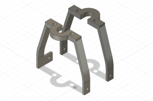 |
Holder Brackets bracket_back.stl bracket_front.stl bracket_front_cable_guidance.stl (extended version with a small cable guidance clip for the motor cables) |
If you have any problems to push or move the tool, you have to double-check and tune the tolerances of all 3D-printed part by sanding or grinding the affected parts.
7.2 Assembly of the Motor Control Unit
| Image | Part | Description |
|---|---|---|
|
High-temperature ABS Filament Print temperature: 270°C |
ABS can be mechanized, polished, sanded, drilled and glued and the finish is still good. In addition, it is extremely strong, more heat-resistant and it has certain flexibility. All of which makes it the perfect material for the rapid iron-on tool. We used Tiertime UP Fila ABS. |
|
M2 Screws l=8mm or l=18mm (see options below) |
The M2 screws fit into the threaded inserts and allow us to strongly screw different parts together. M2 screws can be bought in different sizes at many local hardware stores. |
|
Threaded Inserts M2*0.4 / M4.5*0.5; 6mm; SKU: GS08040-01 |
We use threaded inserts to create reusable as well as strong screw connections between the different parts of the additional cable guidance clip. Available, for example, on Amazon. |
| 3D Model | Description |
|---|---|
 |
Motor Control Mounting Cable Motor_Control_Mounting_Cable.stl |
 |
Motor Control Mounting Iron Motor_Control_Mounting_Iron.stl |
 |
Additional Cable Guidance for the RIO Tool Cable_Guidance_Part_01.stl Cable_Guidance_Part_02.stl |
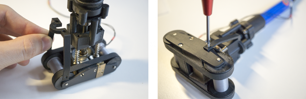
The motor control electronics can be easily attached to the cable or to the iron itself depending on the user preferences. Therefore, you just have to use the 3D-printed brackets and matching M2 screws.
Mounting option #01:
Actuated cutting blade control attached to the cable.
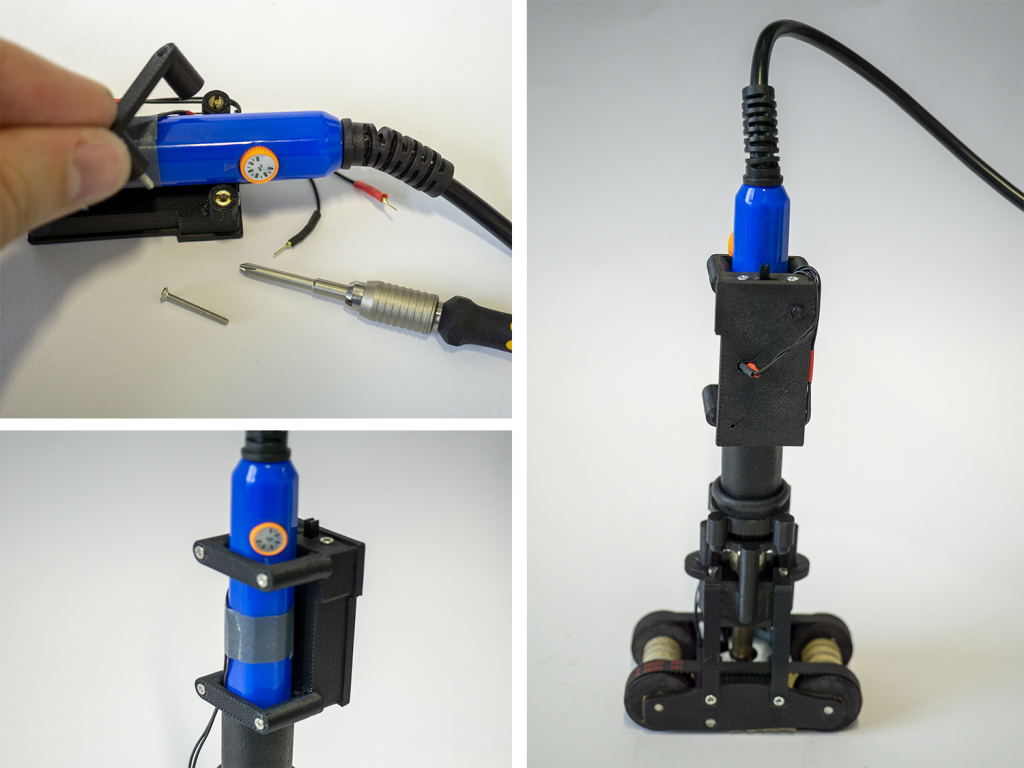
Mounting option #02:
Actuated cutting blade control attached to the tool.
Step 8: Final Check
- Check that the wheels are running smoothly and that the device can be pushed correctly.
- Double-check that potentially hot parts have no physical contact with any component of the rapid iron-on tool.
- Carefully validate that the iron is getting hot by using a multimeter with a temperature-measuring instrument (e.g., multimeter).
Tapes and Patches
Spools
Required tools:
FDM 3D Printer
| Image | Part | Description |
|---|---|---|
|
High-temperature ABS Filament Print temperature: 270°C |
ABS can be mechanized, polished, sanded, drilled and glued and the finish is still good. In addition, it is extremely strong, more heat-resistant and it has certain flexibility. All of which makes it the perfect material for the rapid iron-on tool. We used Tiertime UP Fila ABS. |
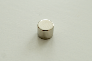 |
Neodymium Magnets Diameter: 5mm, Thickness: 4mm |
We use neodymium magnets to securely fix tapes in the quick-release fasteners spools. Available, for example, on Amazon. |
 |
Steel Tinplate tin-plated in silver, smooth and semi-gloss thickness: 0.17mm |
Available, for example, on Modulor. |
| 3D Model | Description |
|---|---|
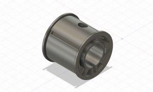 |
Quick-release Fasteners Spool (recommended version) This spool version allows to quickly slide in a tape, magnetically lock it and supports an easy tightening of the spool.quick-release-spool-I-guide.stl (recommended) (compatible with I-guide axis; use this version if you use the freewheel axis) quick-release-spool-U-groove.stl |
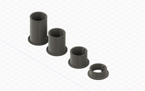 |
Small Basic Spools 1x.stl 2x.stl 3x.stl 4x.stl |
The quick-release fasteners spools consist of a 3D-printed part with a flexible tape fixture (left) as well as a magnetic lock mechanism (right).
Quick-release Fasteners Spool
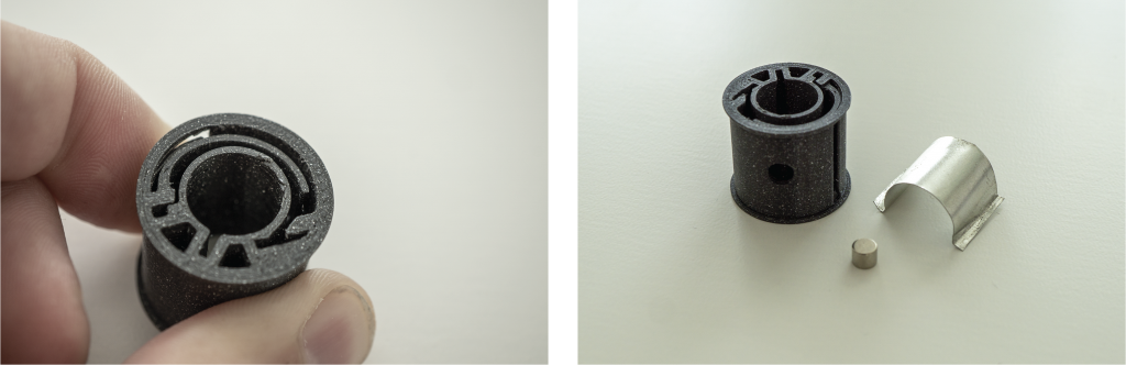
- 3D-print spool.
- Cut and bend metal sheet inlay.
- Place metal piece inside the spool.
- Attach magnet to the spool.
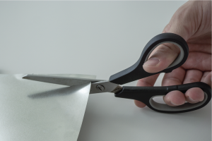
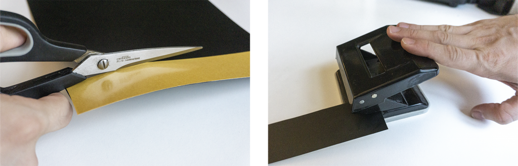
The thin steel tinplate can be easily cut with a scissor.
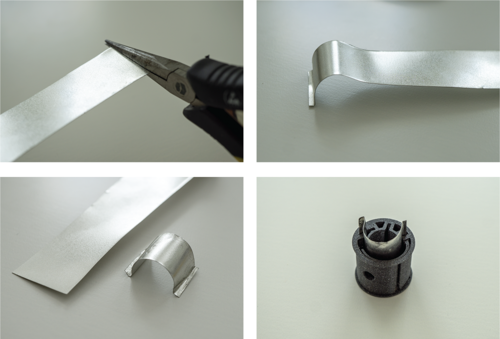
To realize the magnetic lock mechanism, we placed a small piece of metal inside the spool. Therefore, we first cut a tape out of the metal sheet, form it with pliers and finally place it in the spool.
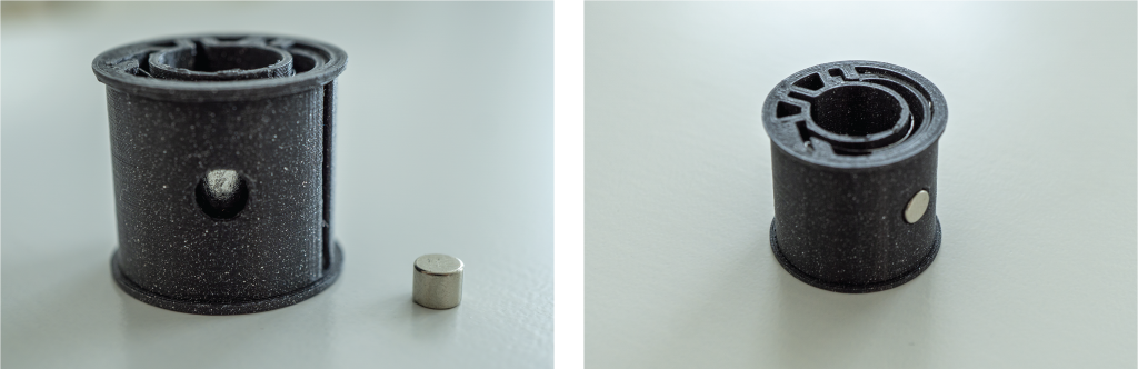
The completed spool consists of two parts: the 3D-printed spool with the metal sheet inside and a magnet (left). If you want to fix a tape you can use the magnet that seamlessly snaps in (right).
Carrier Layer
In order to hold the layout of the functional material in position until it is actually transferred to the textile, we used a heat-resistant carrier layer that is made of baking paper and sticky glue.
Required tools:
Something to make holes (e.g., office puncher, punch pliers, or hole puncher)
| Image | Part | Description |
|---|---|---|
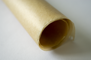 |
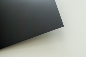
Baking Paper on a roll |
We utilized standard baking paper on a roll that is available in most supermarkets. Please do not use special coated baking papers (e.g., with knobbed surfaces) since they will not work properly with the sticky glue. If you did not find suitable baking paper in your local supermarket, you can also order it online (e.g., Amazon). Pre cut baking paper sheets can be used for iron-on patches, but are not suitable for iron-on tapes since they are limited in their length. |
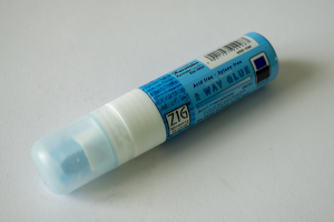 |
Sticky Glue Zig 2-Way Glue, Jumbo Tip |
In order to create a sticky surface, we used a Zig 2-Way Glue Pen that is blue when wet and turns clear when dry. We let the glue dry to create a tacky or sticky adhesive that is able to hold the conductive iron-on materials, but also allows to easily peel-off/dispense the material while ironing. Available, for example, on Modulor. |
 |
Rigid-PVC flexible yet sturdy, thickness: 0.3mm |
We used a small piece of a thin and flexible PVC film to strengthen connection mechanism of the tapes’ beginning and end. Available, for example, on Modulor. |
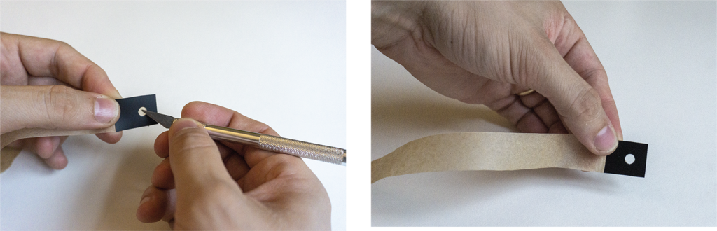
Baking Paper Tape
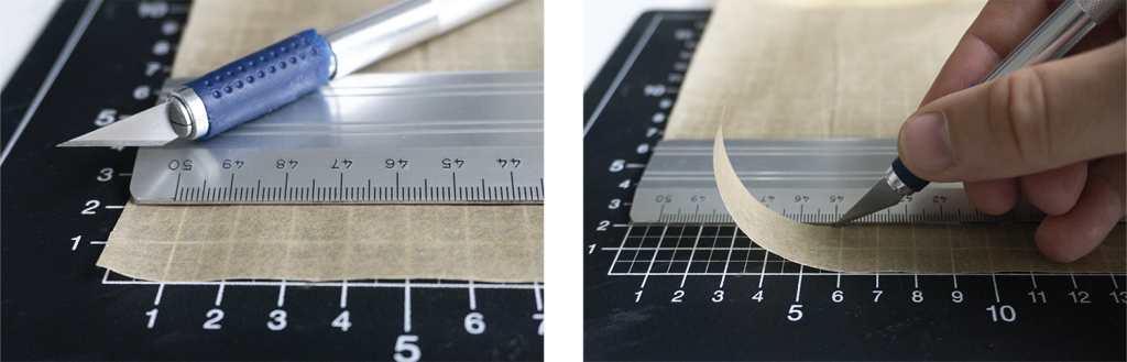
First, you have to cut a tape out of the baking paper in the desired length and width. Therefore, we use a cutting base, a ruler and a hobby knife. If you want to use the full width of the rapid iron-on device you have to choose a width of 2 centimeters.
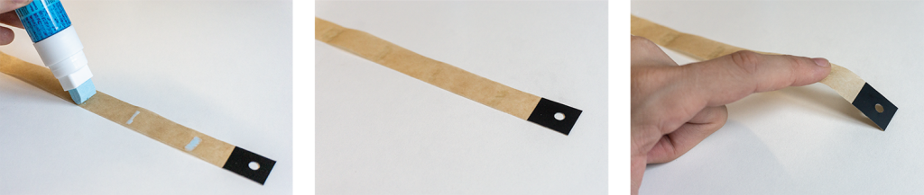
Quick Release Connectors
In order to prepare the iron-on tape for the quick-release fasteners spool, we fabricated strengthened ends made of PVC foil.
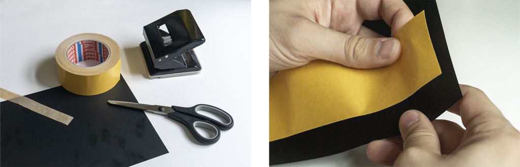
To strengthen the connection of the tape, we preapre PVC foil with double-sided adhesive tape, cut the PVC foil and create a hole by using a office puncher.
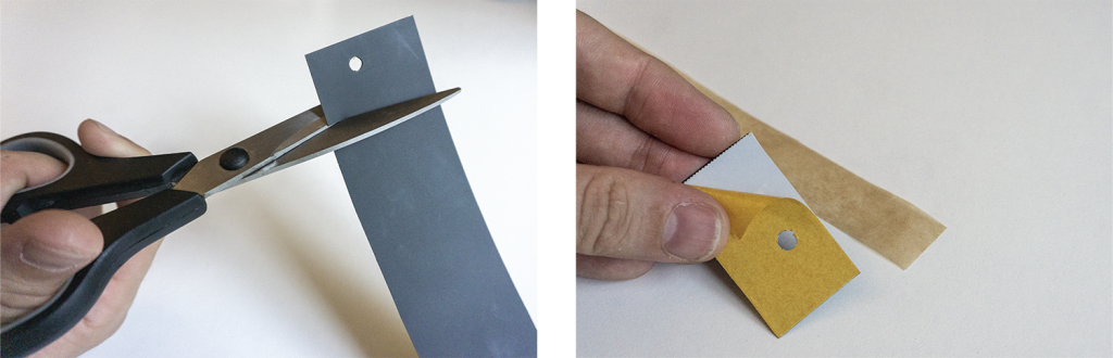
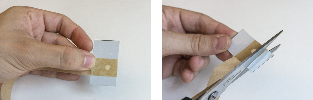
Finally, you have to glue and cut the stencil and cut again a hole. The result is a carrier tape that is ready to use with the quick-release fasteners spool.
Sticky Coating
- Use the zig 2-way glue to coat the previously created tape.
- For most iron-on components small adhesive strips at regular intervals work.
- Wait until the blue glue turns clear and became sticky.
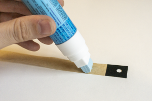
For most Iron-On Tapes small adhesive strips at regular intervals work fine. If you need more adhesive power you can also coat the tape with more glue, however, you have to find a good balance between a suitable adhesion on the carrier layer as well as ensure a smooth peel off during the ironing process.
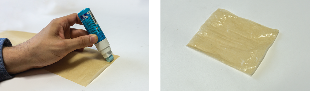
In contrast, Iron-On Patches could be always completely coated with sticky glue since the peel off process is executed manually.
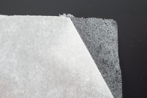
Functional Layer
| Image | Part | Description |
|---|---|---|
 |
Conductive Fabric Shieldex Zell RS; Prod. No.: 163272 |
A variety of conductive fabrics are available. In order to realize the trace spools we used ultra-thin, high-conductive metalized fabrics from Shieldex (Zell). You can find further technical datasheets as well as ordering options on Statex.de. |
 |
Fusible Web Vliesofix/Bondaweb Prod. No.: 4008983220107 |
We used standard Vliesofix/Bondaweb as adhesive layer. Therefore, we ironed the fusible web to the conductive fabric before we cut the functional layer and did not remove the protection layer from it at this stage. This helps us to fix/glue the fusible web and conductive fabric stack to a sacrificial plate before cutting. Vliesofix/Bondaweb is available at many local textile DIY crafting shops or online (e.g., Amazon). |
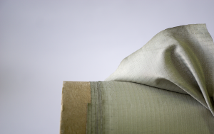
Traces
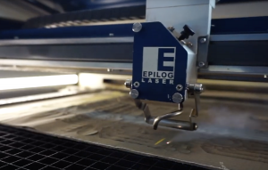
Lasercut
We used an Epilog Fusion 40 M2 lasercutter to fabricate many conductive fabric parts. Please note that we bonded the fusible web layer before we lasercut the fabric.
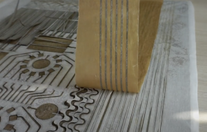
Peel-off
Next, we removed all unnecessary fabric parts and transferred the traces by using baking paper that we coated with sticky glue beforehand.
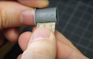
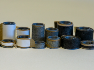
Roll onto spools
Finally, the transferred traces need to be cut and rolled onto a spool.
Press Coverage
Rapid iron-on user interfaces is also discussed in the DIY communities and blogs:
by Kristina Panos, hackaday.com